MJF44H11G(2006) 查看數據表(PDF) - ON Semiconductor
零件编号
产品描述 (功能)
生产厂家
MJF44H11G Datasheet PDF : 5 Pages
| |||
MJF44H11 (NPN),
MJF45H11 (PNP)
Preferred Devices
Complementary
Power Transistors
For Isolated Package Applications
Complementary power transistors are for general purpose power
amplification and switching such as output or driver stages in
applications such as switching regulators, converters and power
amplifiers.
Features
• Low Collector−Emitter Saturation Voltage −
VCE(sat) = 1.0 V (Max) @ 8.0 A
• Fast Switching Speeds
• Complementary Pairs Simplifies Designs
• Pb−Free Packages are Available*
MAXIMUM RATINGS
Rating
Symbol Value
Unit
Collector−Emitter Voltage
ÎÎÎÎÎÎÎÎÎÎÎÎÎÎÎÎÎÎÎ Emitter−Base Voltage
ÎÎÎÎÎÎÎÎÎÎÎÎÎÎÎÎÎÎÎ Collector Current − Continuous
ÎÎÎÎÎÎÎÎÎÎÎÎÎÎÎÎÎÎÎ − Peak
VCEO
80
Vdc
VEB
5
Vdc
IC
10
Adc
20
ÎÎÎÎÎÎÎÎÎÎÎÎÎÎÎÎÎÎÎ Total Power Dissipation
ÎÎÎÎÎÎÎÎÎÎÎÎÎÎÎÎÎÎÎ @ TC = 25°C
Derate above 25°C
PD
36
W
1.67
W/°C
ÎÎÎÎÎÎÎÎÎÎÎÎÎÎÎÎÎÎÎ Total Power Dissipation
ÎÎÎÎÎÎÎÎÎÎÎÎÎÎÎÎÎÎÎ @ TA = 25°C
Derate above 25°C
PD
2.0
W
0.016
W/°C
ÎÎÎÎÎÎÎÎÎÎÎÎÎÎÎÎÎÎÎ Operating and Storage Junction
ÎÎÎÎÎÎÎÎÎÎÎÎÎÎÎÎÎÎÎ Temperature Range
TJ, Tstg −55 to 150 °C
ÎÎÎÎÎÎÎÎÎÎÎÎÎÎÎÎÎÎÎ THERMAL CHARACTERISTICS
ÎÎÎÎÎÎÎÎÎÎÎÎÎÎÎÎÎÎÎ Characteristic
Symbol
Max
Unit
ÎÎÎÎÎÎÎÎÎÎÎÎÎÎÎÎÎÎÎ Thermal Resistance, Junction−to−Case
RqJC
3.5
°C/W
ÎÎÎÎÎÎÎÎÎÎÎÎÎÎÎÎÎÎÎ Thermal Resistance, Junction−to−Ambient RqJA
62.5
°C/W
ÎÎÎÎÎÎÎÎÎÎÎÎÎÎÎÎÎÎÎ Maximum ratings are those values beyond which device damage can occur.
Maximum ratings applied to the device are individual stress limit values (not
normal operating conditions) and are not valid simultaneously. If these limits are
exceeded, device functional operation is not implied, damage may occur and
reliability may be affected.
*For additional information on our Pb−Free strategy and soldering details, please
download the ON Semiconductor Soldering and Mounting Techniques
Reference Manual, SOLDERRM/D.
© Semiconductor Components Industries, LLC, 2006
1
April, 2006 − Rev. 4
http://onsemi.com
SILICON POWER TRANSISTORS
10 AMPERES
80 VOLTS, 36 WATTS
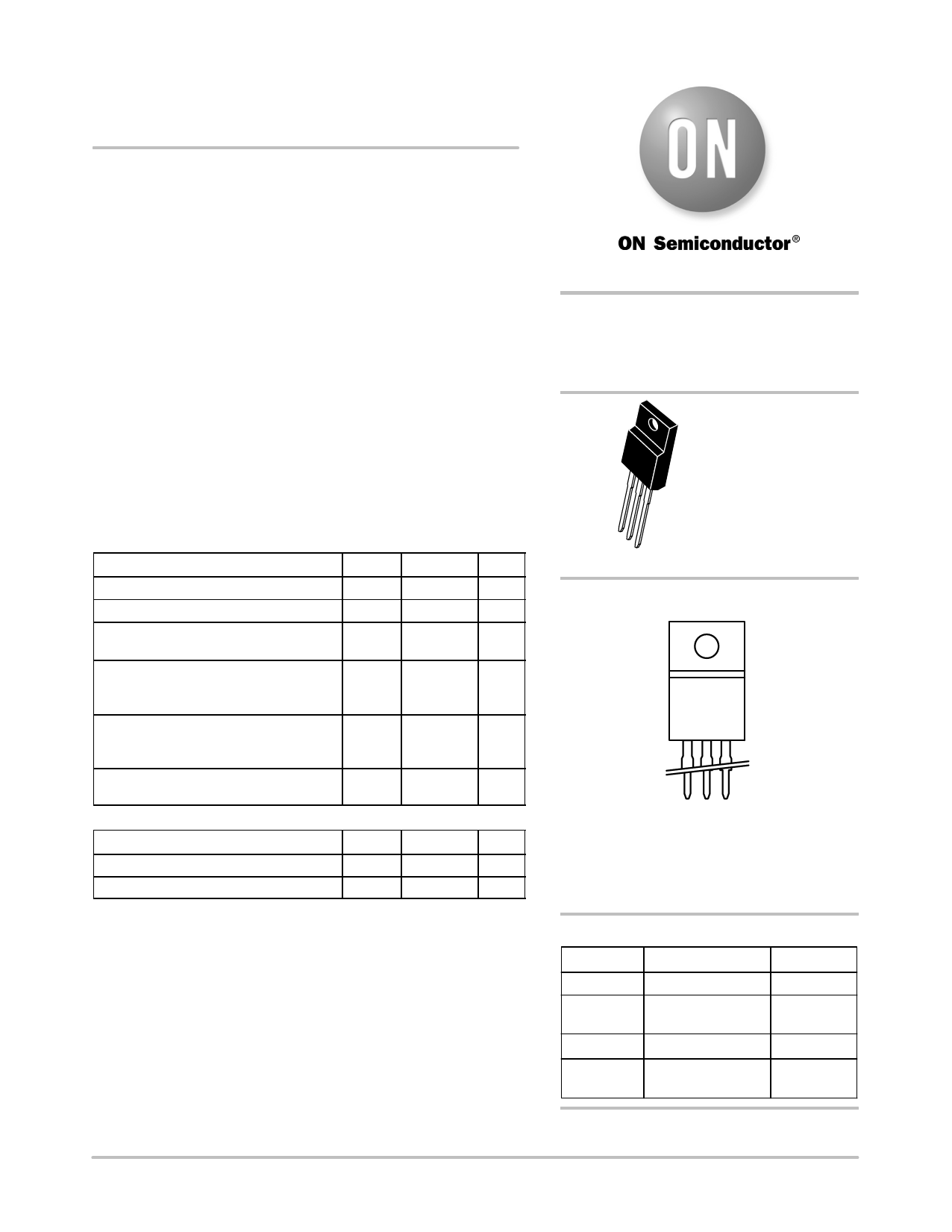
1
23
ISOLATED TO−220
CASE 221D
STYLE 2
MARKING DIAGRAM
F4xH11G
AYWW
F4xH11 = Specific Device Code
x = 4 or 5
G
= Pb−Free Package
A
= Assembly Location
Y
= Year
WW = Work Week
ORDERING INFORMATION
Device
Package
Shipping
MJF44H11 TO−220 FULLPACK 50 Units/Rail
MJF44H11G TO−220 FULLPACK 50 Units/Rail
(Pb−Free)
MJF45H11 TO−220 FULLPACK 50 Units/Rail
MJF45H11G TO−220 FULLPACK 50 Units/Rail
(Pb−Free)
Preferred devices are recommended choices for future use
and best overall value.
Publication Order Number:
MJF44H11/D
Share Link: 