PF0121 查看數據表(PDF) - Hitachi -> Renesas Electronics
零件编号
产品描述 (功能)
生产厂家
PF0121 Datasheet PDF : 12 Pages
| |||
PF0121
Electrical Characteristics (Tc = 25°C)
Item
Drain cutoff current
Total efficiency
2nd harmonic distortion
3rd harmonic distortion
Input VSWR
Output power (1)
Output power (2)
Isolation
Switching time
Stability
Symbol Min
I DS
—
ηT
30
2nd H.D. —
3rd H.D. —
VSWR (in) —
Pout (1) 17
Typ Max Unit
— 500 µA
35 — %
–50 –40 dBc
–55 –45 dBc
2
3
—
23 — W
Pout (2) 9
12 — W
—
— –60 –40 dBm
tr, tf
— 1.5 2
µs
—
No parasitic oscillation —
Test Condition
VDD = 17 V, VAPC = 0 V
Pin = 2 mW, VDD = 12.5 V,
Pout = 13 W (at APC controlled),
RL = Rg = 50 Ω, Tc = 25°C
Pin = 2 mW, VDD = 12.5 V, VAPC = 7 V,
RL =Rg = 50 Ω, Tc = 25°C
Pin = 2 mW, VDD = 10.3V, VAPC = 7 V,
RL = Rg = 50 Ω, Tc = 80°C
Pin = 2 mW, VDD = 12.5 V, VAPC = 0.5 V,
RL = Rg = 50 Ω, Tc = 25°C
Pin = 2 mW, VDD = 12.5 V, Pout = 13 W,
RL = Rg = 50 Ω, Tc = 25°C
Pin = 2 mW, VDD = 12.5 V,
Pout ≤ 13 W (at APC controlled),
Rg = 50 Ω, Tc = 25°C,
Output VSWR = 20:1 All phases
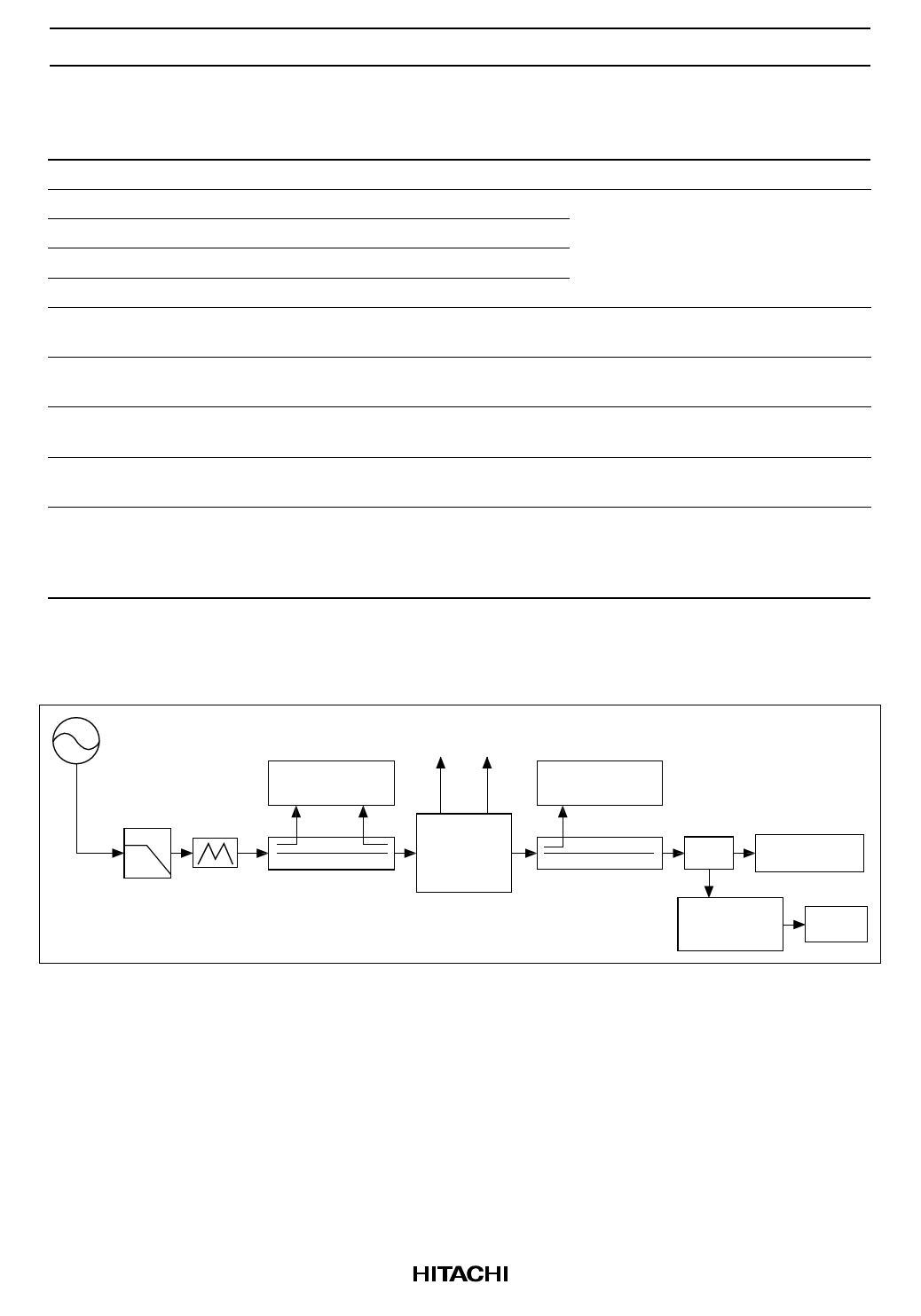
Test System Diagram
S.G
L.P.F 3dB
ATT
Power
Meter
Directional
Coupler
VAPC VDD
Test
Fixture
Spectrum
Analyzer
Directional
Coupler
RF SW. Power Meter
Phase
Shifter
Short
3
Share Link: 