10A05 查看數據表(PDF) - Formosa Technology
零件编号
产品描述 (功能)
生产厂家
10A05 Datasheet PDF : 6 Pages
| |||
Axial Leaded General Purpose Rectifiers
10A05 THRU 10A10
10.0A Axial Leaded General Purpose
Rectifiers - 50V-1000V
Features
• Low forward voltage drop.
• High current capability.
• High surge current capability.
• High reliability.
• Silicon rubber coating chip junction.
• Lead-free parts meet environmental standards of
MIL-STD-19500 /228
• Suffix "-H" indicates Halogen-free parts, ex. 10A05-H.
Mechanical data
• Epoxy : UL94-V0 rated flame retardant
• Case : Molded plastic, P600
• Lead : Axial leads, solderable per MIL-STD-202,
Method 208 guranteed
• Polarity: Color band denotes cathode end
• Mounting Position : Any
• Weight : Approximated 1.75 gram
Formosa MS
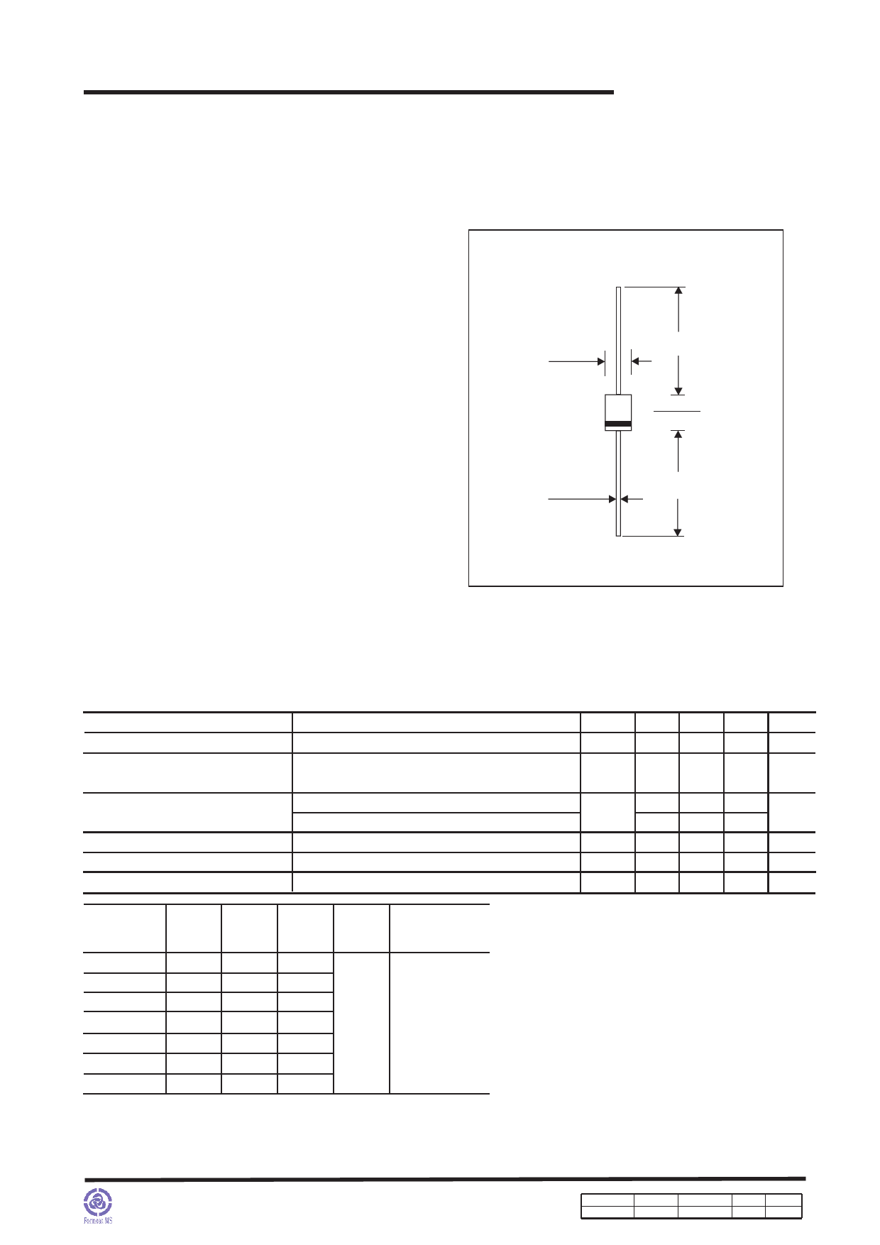
Package outline
P600
.360(9.10)
.340(8.60)
1.0(25.4)
MIN.
.360(9.10)
.340(8.60)
.052(1.32)
.048(1.22)
1.0(25.4)
MIN.
Dimensions in inches and (millimeters)
Maximum ratings and Electrical Characteristics (AT TA=25oC unless otherwise noted)
PARAMETER
CONDITIONS
Symbol MIN. TYP. MAX. UNIT
Forward rectified current
See Fig.1
IO
10.0 A
Forward surge current
Reverse current
Thermal resistance
Diode junction capacitance
Storage temperature
8.3ms single half sine-wave (JEDEC methode)
IFSM
400
A
VR = VRRM TJ = 25OC
VR = VRRM TJ = 100OC
Junction to Ambient .375" (9.5mm) lead length
f=1MHz and applied 4V DC reverse voltage
IR
RθJA
CJ
TSTG
10
uA
400
10
OC/W
150
pF
-65
+150 OC
SYMBOLS
10A05
10A1
10A2
10A4
10A6
10A8
10A10
*1
VRRM
(V)
50
100
200
400
600
800
1000
V
*
RMS
2
(V)
35
70
140
280
420
560
700
*3
VR
(V)
50
100
200
400
600
800
1000
*4
VF
(V)
1.00
Operating
temperature
TJ, (OC)
-55 to +125
*1 Repetitive peak reverse voltage
*2 RMS voltage
*3 Continuous reverse voltage
*4 Maximum forward voltage@IF=10.0A
http://www.formosams.com/
TEL:886-2-22696661
FAX:886-2-22696141
Page 2
Document ID Issued Date
DS-222130 2010/06/10
Revised Date Revision
2010/08/10
B
Page.
6
Share Link: 