KSZ9031MNX View Datasheet(PDF) - Micrel
Part Name
Description
Manufacturer
KSZ9031MNX Datasheet PDF : 77 Pages
| |||
Micrel, Inc.
KSZ9031MNX
Strapping Options
Pin Number
48
17
19
Pin Name
PHYAD2
PHYAD1
PHYAD0
39
MODE3
41
MODE2
43
MODE1
44
MODE0
45
CLK125_EN
55
LED_MODE
Note:
1. I/O = Bi-directional.
Type(1)
I/O
I/O
I/O
I/O
I/O
I/O
I/O
I/O
I/O
Pin Function
The PHY address, PHYAD[2:0], is sampled and latched at power-up/reset and is
configurable to any value from 0 to 7. Each PHY address bit is configured as follows:
Pull-up = 1
Pull-down = 0
PHY address bits [4:3] are always set to ‘00’.
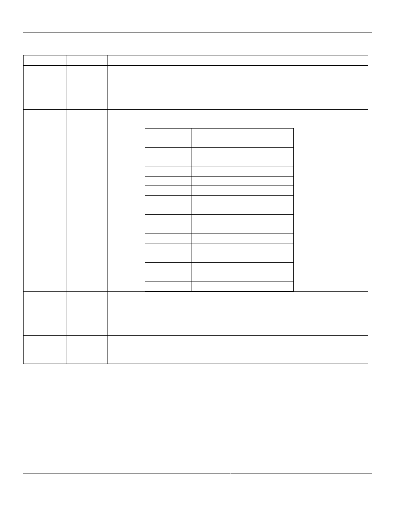
The MODE[3:0] strap-in pins are sampled and latched at power-up/reset and are
defined as follows:
MODE[3:0]
Mode
0000
Reserved – not used
0001
GMII/MII mode
0010
Reserved – not used
0011
Reserved – not used
0100
NAND tree mode
0101
Reserved – not used
0110
Reserved – not used
0111
Chip power-down mode
1000
Reserved – not used
1001
Reserved – not used
1010
Reserved – not used
1011
Reserved – not used
1100
Reserved – not used
1101
Reserved – not used
1110
Reserved – not used
1111
Reserved – not used
CLK125_EN is sampled and latched at power-up/reset and is defined as follows:
Pull-up (1) = Enable 125MHz clock output
Pull-down (0) = Disable 125MHz clock output
Pin 55 (CLK125_NDO) provides the 125MHz reference clock output option for use by
the MAC.
LED_MODE is sampled and latched at power-up/reset and is defined as follows:
Pull-up (1) = Single-LED mode
Pull-down (0) = Tri-color dual-LED mode
Pin strap-ins are latched during power-up or reset. In some systems, the MAC receive input pins may be driven during the
power-up or reset process, and consequently cause the PHY strap-in pins on the GMII/MII signals to be latched to the
incorrect configuration. In this case, Micrel recommends adding external pull-up or pull-down resistors on the PHY strap-in
pins to ensure the PHY is configured to the correct pin strap-in mode.
October 2012
16
M9999-103112-1.0
Share Link: 