MAX6653 View Datasheet(PDF) - Maxim Integrated
Part Name
Description
Manufacturer
MAX6653 Datasheet PDF : 24 Pages
| |||
Temperature Monitors and
PWM Fan Controllers
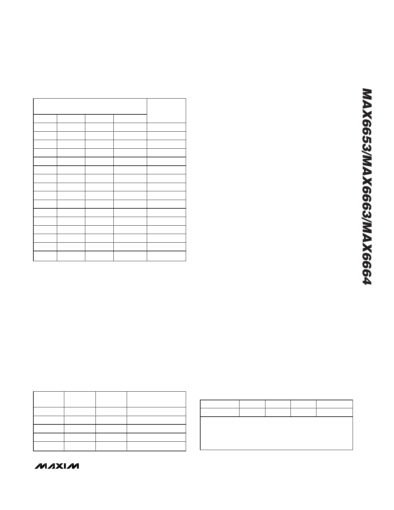
Table 9. Setting PWM Duty Cycle
BITS [3:0] OF FAN-SPEED
CONFIGURATION REGISTER (22h)
BIT 3 BIT 2
BIT 1
BIT 0
0
0
0
0
0
0
0
1
0
0
1
0
0
0
1
1
0
1
0
0
0
1
0
1
0
1
1
0
0
1
1
1
1
0
0
0
1
0
0
1
1
0
1
0
1
0
1
1
1
1
0
0
1
1
0
1
1
1
1
0
1
1
1
1
% DUTY
CYCLE (%)
0
7
14
20
27
33
40
47
53
60
67
73
80
87
93
100
Automatic Fan-Control Mode
Automatic fan-speed control is selected by setting bits
[7:5] of configuration register 1 (00h) to 100 (to control
speed based on the remote temperature) or 101 (to
control speed based on both remote and local temper-
ature). Program a threshold, or starting temperature
TMIN, and the desired temperature range, TRANGE, into
the local temp TMIN/TRANGE register (24h) for local
temperature and into the remote temp TMIN/TRANGE
register (25h) for remote temperature (Tables 10 and
11). If the fan control responds to both local and remote
temperatures, the higher PWM duty cycle has priority.
Table 10. TRANGE Fan-Control Temperature
Range Bits [2:0] TMIN/TRANGE Registers
(24h and 25h)—POR = 001
BIT 2
BIT 1
BIT 0
TEMPERATURE
RANGE (°C)
0
0
0
5
0
0
1
10
0
1
0
20
0
1
1
40
1
0
0
80
When the temperature exceeds TMIN, the fan is
enabled at a minimum duty cycle programmed in bits
[3:0] of the fan-speed configuration register (22h). The
duty cycle increases in proportion to the temperature
difference and reaches 100% at a temperature equal to
(TMIN + TRANGE). A hysteresis of 5°C is built into the
TMIN set point to prevent the fan from starting and stop-
ping when the temperature is at the set point.
Spin-Up
To ensure proper fan startup, the MAX6653/MAX6663/
MAX6664 can be set to drive the fan to 100% duty
cycle for a short period on startup, and then revert to
the correct duty cycle. The spin-up time is programmed
by bits [2:0] in the fan characteristics register (20h).
The spin-up feature can be disabled by setting bit 7 of
the fan-filter register (23h) to 1; POR value is zero.
Table 12 shows programming of the spin-up time.
Fan-Filter Mode
When the MAX6653/MAX6663/MAX6664 are used for
automatic fan-speed control, the fan-filter mode helps
minimize the audible effects of varying fan speeds. The
fan-filter mode limits the rate at which fan speed can
change. Each time a new temperature measurement is
made, the fan-filter mode allows the PWM duty cycle to
increment by a selectable amount. The duty cycle can
change by 1/240, 2/240, 4/240, or 8/240 (0.416%,
0.833%, 1.667%, or 3.333%) of the PWM period after
each temperature-monitoring cycle. This prevents sud-
den changes in fan speed, even when temperature
changes suddenly.
The filter mode is set by bit 0 of the fan-filter register
(23h). To enable the fan-filter mode, write a 1 to this bit.
Bits [6:5] of the same register control the size of the
PWM steps.
Note that the rate of change depends on both the value
selected by the fan-filter bits and on the temperature
Table 11.TMIN Fan-Control Start
Temperature; Bits [7:3] TMIN/TRANGE
Registers (24h—POR = 01000 and
25h—POR = 01100
BIT 7
MSB = +64°C
BIT 6
BIT5
BIT 4
BIT3
LSB = +4°C
Min threshold = 0°C
Max threshold = +127°C
LSB/step size = +4°C
POR = +48°C or 01100b
______________________________________________________________________________________ 11
Share Link: 