SC18IS600(2006) View Datasheet(PDF) - NXP Semiconductors.
Part Name
Description
Manufacturer
SC18IS600 Datasheet PDF : 28 Pages
| |||
NXP Semiconductors
SC18IS600/601
SPI to I2C-bus interface
6.3 External clock input (SC18IS601)
In this device, the processor clock is derived from an external source driving the CLKIN
pin. The clock rate may be from 0 Hz up to 18 MHz.
6.4 I2C-bus serial interface
I2C-bus uses two wires (SDA and SCL) to transfer information between devices connected
to the bus, and it has the following features:
• Bidirectional data transfer between masters and slaves
• Multi-master bus (no central master)
• Arbitration between simultaneously transmitting masters without corruption of serial
data on the bus
• Serial clock synchronization allows devices with different bit rates to communicate via
one serial bus
• Serial clock synchronization can be used as a handshake mechanism to suspend and
resume serial transfer
• The I2C-bus may be used for test and diagnostic purposes.
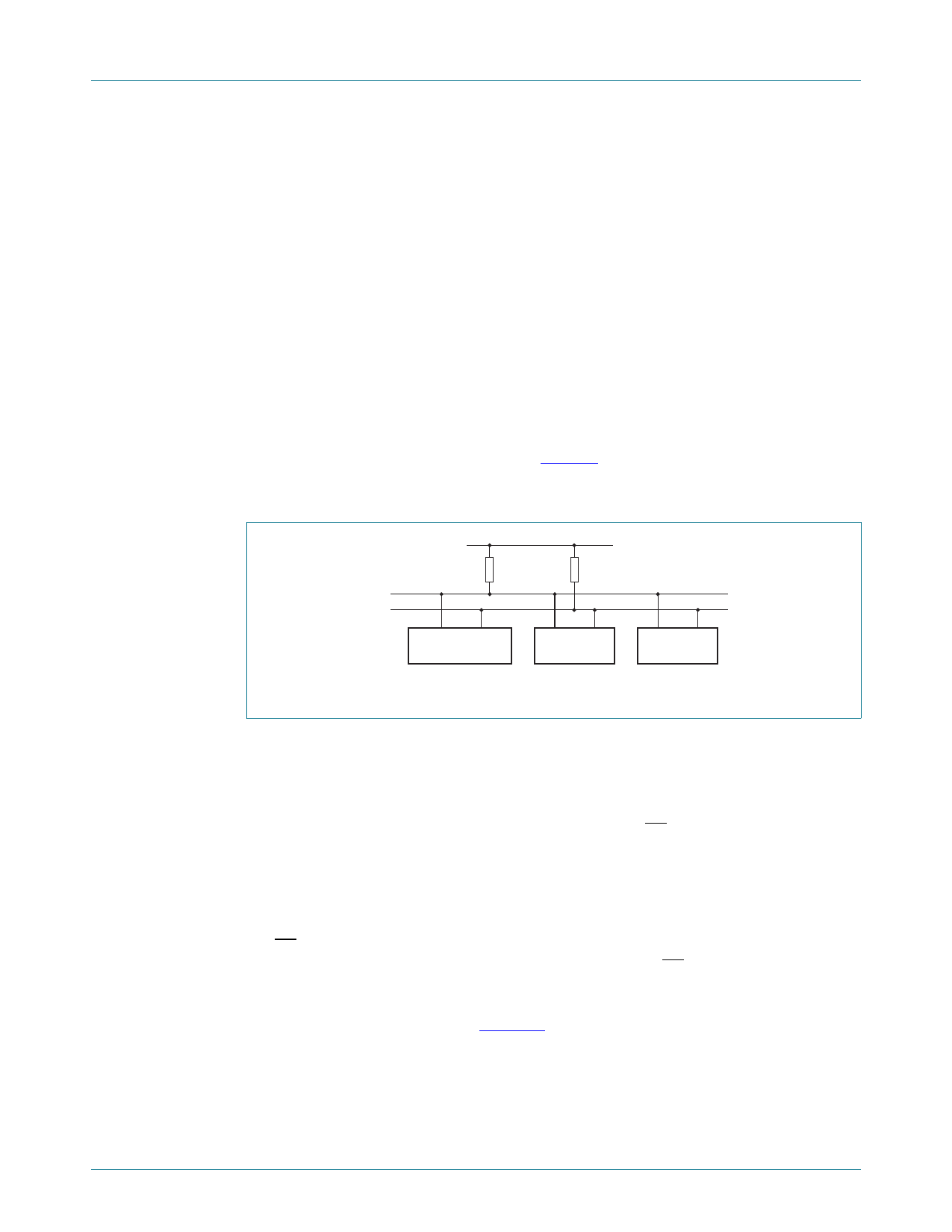
A typical I2C-bus configuration is shown in Figure 10. The SC18IS600/601 device
provides a byte-oriented I2C-bus interface that supports data transfers up to 400 kHz.
(Refer to Philips Semiconductors The I2C-bus specification, document order number
9398 393 40011.)
I2C-bus
VDD
RPU
SC18IS600/601
RPU
I2C-BUS
DEVICE
Fig 10. I2C-bus configuration
SDA
SCL
I2C-BUS
DEVICE
002aab716
6.5 Serial Peripheral Interface (SPI)
The host communicates with the SC18IS600/601 via the SPI interface. The
SC18IS600/601 operates in Slave mode up to 3 Mbit/s.
The SPI interface has four pins: SCLK, MOSI, MISO, and CS.
• SCLK, MOSI and MISO are typically tied together between two or more SPI devices.
Data flows from the master to the SC18IS600/601 on the MOSI (Master Out Slave In)
pin and flows from SC18IS600/601 to the master on the MISO (Master In Slave Out)
pin. The SCLK signal is an input to the SC18IS600/601.
• CS is the slave select pin. In a typical configuration, an SPI master selects one SPI
device as the current slave. An SPI slave device uses its CS pin to determine whether
it is selected. The CS pin may be tied LOW if it is the only device on the bus.
Typical connections are shown in Figure 11.
SC18IS600_601_3
Product data sheet
Rev. 03 — 13 December 2006
© NXP B.V. 2006. All rights reserved.
11 of 28
Share Link: 