MAX4295 View Datasheet(PDF) - Maxim Integrated
Part Name
Description
Manufacturer
MAX4295 Datasheet PDF : 18 Pages
| |||
Mono/Stereo 2W Switch-Mode (Class-D)
Audio Power Amplifiers
AOUT
IN
0.3 ✕ VCC
(VCM)
FS1
PWM
FS2
OSC
VCC
SS
POWER MANAGEMENT
AND PROTECTION
CSS
GND
PVCC
GATE
DRIVE
OUT+
PGND
PVCC
GATE
OUT-
DRIVE
PGND
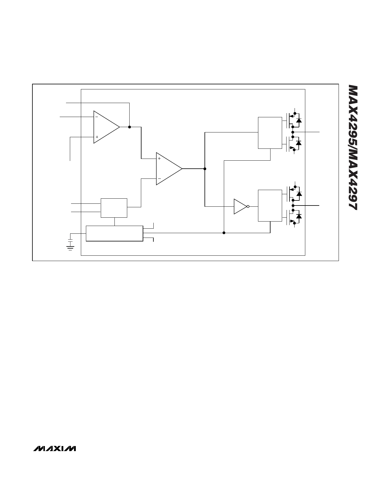
Figure 1a. MAX4295 Functional Diagram
H-bridge. The switches work in pairs to reverse the
polarity of the signal in the load. Break-before-make
switching of the H-bridge MOSFETs by the driver circuit
keeps supply current glitches and crowbar current in
the MOSFETs at a low level. The output swing of the H-
bridge is a direct function of the supply voltage.
Varying the oscillator swing in proportion to the supply
voltage maintains constant gain with varying supply
voltage.
FS1 and FS2 program the oscillator to a frequency of
125kHz, 250kHz, 500kHz, and 1MHz. The sawtooth
oscillator swings between GND and 0.6 ✕ VCC. The
input signal is typically AC-coupled to the internal input
op amp, whose gain can be controlled through external
feedback components. The common-mode voltage of
the input amplifier is 0.3 ✕ VCC and is internally gener-
ated from the same resistive divider used to generate
the 0.6 ✕ VCC reference for the PWM oscillator.
Current Limit
A current-limiting circuit in the H-bridge monitors the
current in the H-bridge transistors and disables the H-
bridge if the current in any of the H-bridge transistors
exceeds 1A. The H-bridge is enabled after a period of
100µs. A continuous short circuit at the output results in
a pulsating output.
Thermal Overload Protection
Thermal overload protection limits total power dissipa-
tion in the MAX4295/MAX4297. When the junction tem-
perature exceeds +145°C, the thermal detection
disables the H-bridge transistors. The H-bridge transis-
tors are enabled after the IC’s junction temperature
cools by 10°C. This results in a pulsating output under
continuous thermal overload conditions. Junction tem-
perature does not exceed the thermal overload trip
point in normal operation, but only in the event of fault
conditions, such as when the H-bridge outputs are
short circuited.
Undervoltage Lockout
At low supply voltages, the MOSFETs in the H-bridge
may have inadequate gate drive thus dissipating
excessive power. The undervoltage lockout circuit pre-
vents the device from operating at supply voltages
below +2.2V.
______________________________________________________________________________________ 11
Share Link: 