S25FL016A View Datasheet(PDF) - Spansion Inc.
Part Name
Description
Manufacturer
S25FL016A
Spansion Inc.

S25FL016A Datasheet PDF : 36 Pages
| |||
Data Sheet
6. Spansion SPI Modes
A microcontroller can use either of its two SPI modes to control Spansion SPI Flash memory devices:
CPOL = 0, CPHA = 0 (Mode 0)
CPOL = 1, CPHA = 1 (Mode 3)
Input data is latched in on the rising edge of SCK, and output data is available from the falling edge of SCK for
both modes.
When the bus master is in standby mode, SCK is as shown in Figure 6.2 for each of the two modes:
SCK remains at 0 for (CPOL = 0, CPHA = 0 Mode 0)
SCK remains at 1 for (CPOL = 1, CPHA = 1 Mode 3)
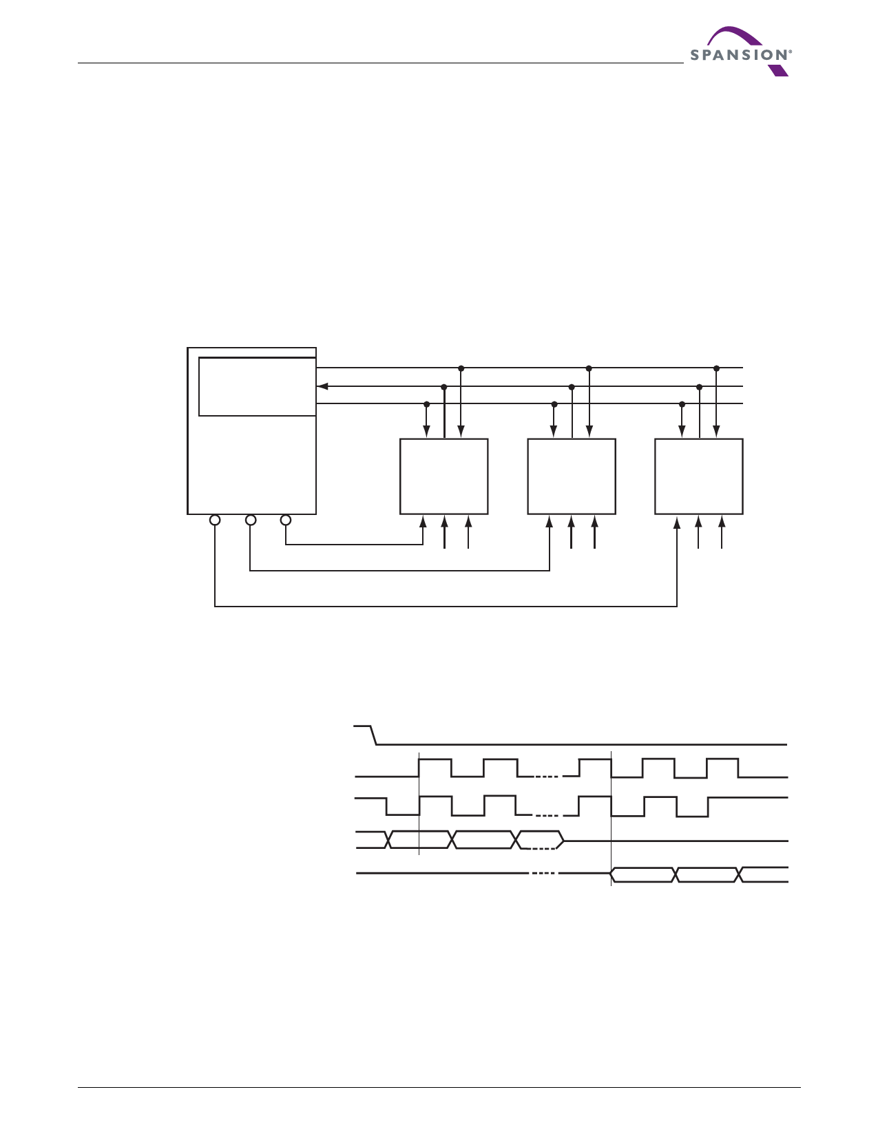
Figure 6.1 Bus Master and Memory Devices on the SPI Bus
SO
SPI Interface with
SI
(CPOL, CPHA) =
(0, 0) or (1, 1)
SCK
Bus Master
SCK SO SI
SCK SO SI
SCK SO SI
CS3 CS2 CS1
SPI Memory
Device
SPI Memory
Device
SPI Memory
Device
CS#
W# HOLD#
CS#
W# HOLD#
CS#
W# HOLD#
Note
The Write Protect (W#) and Hold (HOLD#) signals should be driven high (logic level 1) or low (logic level 0) as appropriate.
CS#
CPOL CPHA
Mode 0 0
0 SCK
Mode 3 1
1 SCK
SI
SO
Figure 6.2 SPI Modes Supported
MSB
MSB
January 7, 2008 S25FL016A_00_C3
S25FL016A
11
Share Link: