AS3931 View Datasheet(PDF) - austriamicrosystems AG
Part Name
Description
Manufacturer
AS3931 Datasheet PDF : 31 Pages
| |||
AS3931
Datasheet - Configuring the Product
9.3.4 C5 (WAKE Clear)
Bit C5 is used to reset the active low WAKE pin after the pin has been set as a result of receiving a valid code word (single or double wake
pattern) by one of the 3 channels, a POR or an internally generated Wakeup. Setting Bit C5 to 1, the WAKE pin is reset to high and held in high
state, to enable the channels for the next wake up signal, the bit C5 must be toggled to 0 afterwards. After power on, the WAKE-pin is activated
and the bit C5 has to be toggled high and low after a power on.
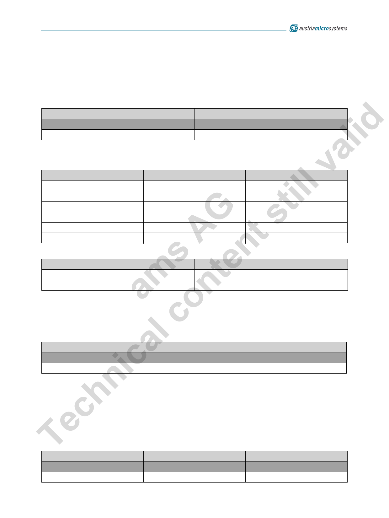
Table 15. C5 Bit Mode
C5
Mode
0
no effect
lid 1
WAKE=H
9.4 Test Mode Register
a Table 16. Register Data
v Bit
T0
ill T1
T2
t T3
G s T4
T5
POR state
0
0
0
0
1
0
Description
Test mode enable
Test mode select Bit 1
Test mode select Bit 2
not used
RSSI step
WAKE Generator on/off
A t Table 17. Register Address
s n Bit
e A0
m t A1
Value
0
1
a n 9.4.1 T0 (Test Mode Enable)
o Bit T0 is used to define the pin function of the WAKE pin. When bit T0 is reset to 0, the WAKE pin is used for normal Wake Up detection (Single
or Double Wakeup from the receiver channels or internally generated wakeup). When bit T0 is set to 1, testmode signals are multiplexed to the
c WAKE pin according to the selected test mode (T1, T2). After power on, the normal wake up detection mode is selected.
l Table 18. T0 Bit Mode
T0
WAKE Pin function
a 0
WAKE
ic1
Test Mode Signals
9.4.2 T1, T2 (Test Mode Select)
n When bit T0 is set to 1, the following signals can be mapped to the WAKE pin. For signal description (see Figure 13).
h DATA: received bit stream of the selected channel
WAKE: detected wake up of the selected channel
c For the DATA and WAKE signal select the desired channel by setting Bits C0 and C1.
Te Table 19. T1, T2 Bit Mode
T1
T2
WAKE Pin Function
0
0
DATA of selected channel
1
0
WAKE of selected channel
www.austriamicrosystems.com/AS3931
Revision 6.2
21 - 30
Share Link: 