AS3931 View Datasheet(PDF) - austriamicrosystems AG
Part Name
Description
Manufacturer
AS3931 Datasheet PDF : 31 Pages
| |||
AS3931
Datasheet - Extended Operation
10.6 Direct DATA Mode
In Direct Data Mode, the received DATA of a selected channel can be mapped to the WAKE pin. The DATA signal is the digital output of the
detector and is normally fed to the correlator, where it is scanned for the WAKE pattern (see Figure 13). To get the DATA signal at the WAKE pin,
follow the steps:
1. Enable Test Mode: set T0 = 1 in Test Mode Register
2. Select Test Mode: set T1 = 0 and T2 = 0 in Test Mode Register
3. Select Channel: set C0 and C1 in the Channel Select Register
The Direct DATA signals can also be mapped to the RSSI pin, which then becomes a digital output pin. To do this, make this step:
lid Select RSSI output mode digital:set C2 = 0 and C3 = 1 in the Channel Select Register
Note: The RSSI pin is only active if the CS signal is active (CS = 1), otherwise RSSI is high Z.
a 10.7 Correlator Modes
Operation of the correlators can be modified regarding the error tolerances for the Zero-Half-Bits. In this case, the number of Zero-Half-Bits that
v is allowed to be invalid can be set from 0 to 2. Please take into account that an increased error tolerance also reduces the immunity against
parasitic wakeups (WAKE detection when no data has been sent, due to noise or interferences).
ill 10.8 Threshold Adaptation Filter Time Constant
Bit M4 is used to switch between a large and a small τ of the detector threshold adaptation filter. A large τ is recommended, because it increases
t the noise margin. A small τ can be used to improve the wake sensitivity when non-specified Wake-Patterns are used.
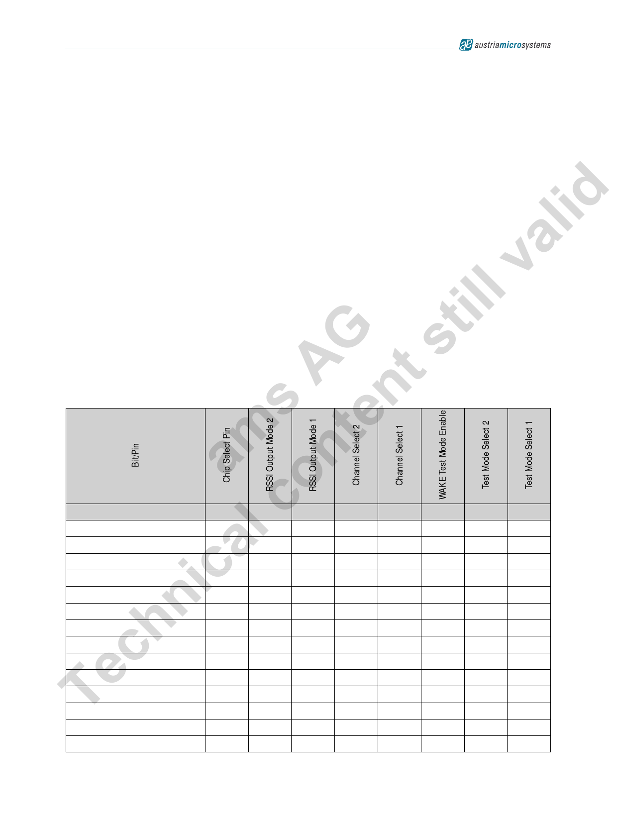
G s 10.9 RSSI and WAKE Pin Modes
A t This table gives an overview of the different signals that can be mapped to the RSSI and WAKE pin and how to program it.
Table 29. RSSI/WAKE-Pin Modes
amsconten Mode
WAKE-Pin: WAKE
l WAKE-Pin: DATA1
a WAKE-Pin: DATA2
ic WAKE-Pin: DATA3
WAKE-Pin: WAKE1
WAKE-Pin: WAKE2
n WAKE-Pin: WAKE3
h RSSI-Pin: WAKE
cRSSI-Pin: DATA1
RSSI-Pin: DATA2
eRSSI-Pin: DATA3
TRSSI-Pin: WAKE1
CS
C3
C2
C1
C0
T0
T2
T1
X
X
X
X
X
0
X
X
X
X
X
0
0
1
0
0
X
X
X
0
1
1
0
0
X
X
X
1
0
1
0
0
X
X
X
0
0
1
0
1
X
X
X
0
1
1
0
1
X
X
X
1
0
1
0
1
1
1
0
1
1
X
X
X
1
1
0
0
0
X
0
0
1
1
0
0
1
X
0
0
1
1
0
1
0
X
0
0
1
1
0
0
0
X
0
1
RSSI-Pin: WAKE2
1
1
0
0
1
X
0
1
RSSI-Pin: WAKE3
1
1
0
1
0
X
0
1
www.austriamicrosystems.com/AS3931
Revision 6.2
26 - 30
Share Link: 