DSP56166 View Datasheet(PDF) - Motorola => Freescale
Part Name
Description
Manufacturer
DSP56166 Datasheet PDF : 63 Pages
| |||
PRELIMINARY - 6/15/93
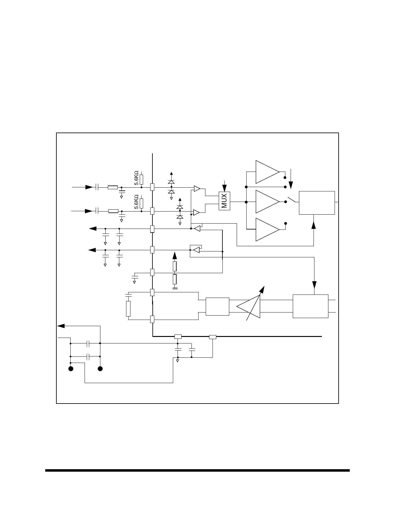
Analog I/O Figure 1. describes the recommended analog I/O and power supply configurations.
The two analog inputs are electrically identical. When one is not used, it can be left floating. When used, an
AC coupling capacitor is required. The value of the capacitor along with the input impedance of the pin de-
termine the cut off frequency of a high pass filter. The input impedance of the MIC and AUX varies as a
function of the ∑∆ modulator master clock. 78 kΩ is a typical value at 2MHz. An AC capacitor of 1µF defines
a high pass filter pole of 2 Hz. A smaller capacitor value will move this pole higher in frequency.
Vrad
1µF 600Ω
Vrad
0.001µF
600Ω
1µF
0.001µF
+
15µF
0.1µF
VssA (≤ ±1mA)
+
15µF
0.1µF
VddA
Mic
VssA
Aux
Vrad
Vrda
INS bit
2.0V ±10%
(2/5 Vdd)
-6dB
6dB
17dB
VssA
< 0.1µF
≤50nF
Vdiv
Spkp
54KΩ
36KΩ
(MAX 1Vp
when single ended
on 0.5KΩ)
digital Vdd
MAX
2Vp
≥1KΩ
digital Vss
0.01µF
220µF
+
Single trace
Spkm
VddA
+
15µF
GND
+5V
Ext. GND Ext. Supply
Single trace
VssA
RC
VssA
VC3-VC0
0.1µF
Analog Decoupling
near DSP
MGS1-0 bits
Σ∆
modulator
2 POLE
LPF
Analog I/O Figure 1. Recommended Analog I/O Configuration
7
DSP56166 Technical Data Sheet
MOTOROLA
Share Link: 