DSP56303UM View Datasheet(PDF) - Freescale Semiconductor
Part Name
Description
Manufacturer
DSP56303UM Datasheet PDF : 108 Pages
| |||
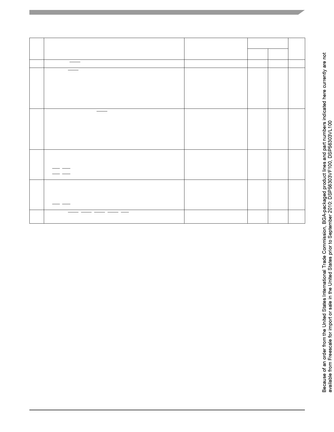
AC Electrical Characteristics
Table 2-7. Reset, Stop, Mode Select, and Interrupt Timing6 (Continued)
No.
Characteristics
Expression
100 MHz
Unit
Min Max
24 Duration for IRQA assertion to recover from Stop state
5.9
—
ns
25 Delay from IRQA assertion to fetch of first instruction (when exiting
Stop)2, 3
• PLL is not active during Stop (PCTL Bit 17 = 0) and Stop delay is
enabled (Operating Mode Register Bit 6 = 0)
PLC × ETC × PDF + (128 K − 1.3
PLC/2) × TC
9.1
ms
• PLL is not active during Stop (PCTL Bit 17 = 0) and Stop delay is not PLC × ETC × PDF + (23.75 ± 232.5 ns 12.3 ms
enabled (Operating Mode Register Bit 6 = 1)
0.5) × TC
• PLL is active during Stop (PCTL Bit 17 = 1) (Implies No Stop Delay)
(8.25 ± 0.5) × TC
87.5
97.5
ns
26 Duration of level sensitive IRQA assertion to ensure interrupt service
(when exiting Stop)2, 3
• PLL is not active during Stop (PCTL Bit 17 = 0) and Stop delay is
PLC × ETC × PDF + (128K − 13.6
—
ms
enabled (Operating Mode Register Bit 6 = 0)
PLC/2) × TC
• PLL is not active during Stop (PCTL Bit 17 = 0) and Stop delay is not
PLC × ETC × PDF +
12.3
—
ms
enabled (Operating Mode Register Bit 6 = 1)
(20.5 ± 0.5) × TC
• PLL is active during Stop (PCTL Bit 17 = 1) (implies no Stop delay)
5.5 × TC
55.0
—
ns
27 Interrupt Requests Rate
• HI08, ESSI, SCI, Timer
• DMA
• IRQ, NMI (edge trigger)
• IRQ, NMI (level trigger)
Maximum:
12 × TC
8 × TC
8 × TC
12 × TC
—
120.0 ns
—
80.0
ns
—
80.0
ns
—
120.0 ns
28 DMA Requests Rate
• Data read from HI08, ESSI, SCI
• Data write to HI08, ESSI, SCI
• Timer
• IRQ, NMI (edge trigger)
Maximum:
6 × TC
7 × TC
2 × TC
3 × TC
—
60.0
ns
—
70.0
ns
—
20.0
ns
—
30.0
ns
29 Delay from IRQA, IRQB, IRQC, IRQD, NMI assertion to external
memory (DMA source) access address out valid
Minimum:
4.25 × TC + 2.0
30.3
—
ns
DSP56303 Technical Data, Rev. 11
Freescale Semiconductor
2-7
Share Link: 