DSP56362 View Datasheet(PDF) - Freescale Semiconductor
Part Name
Description
Manufacturer
DSP56362 Datasheet PDF : 152 Pages
| |||
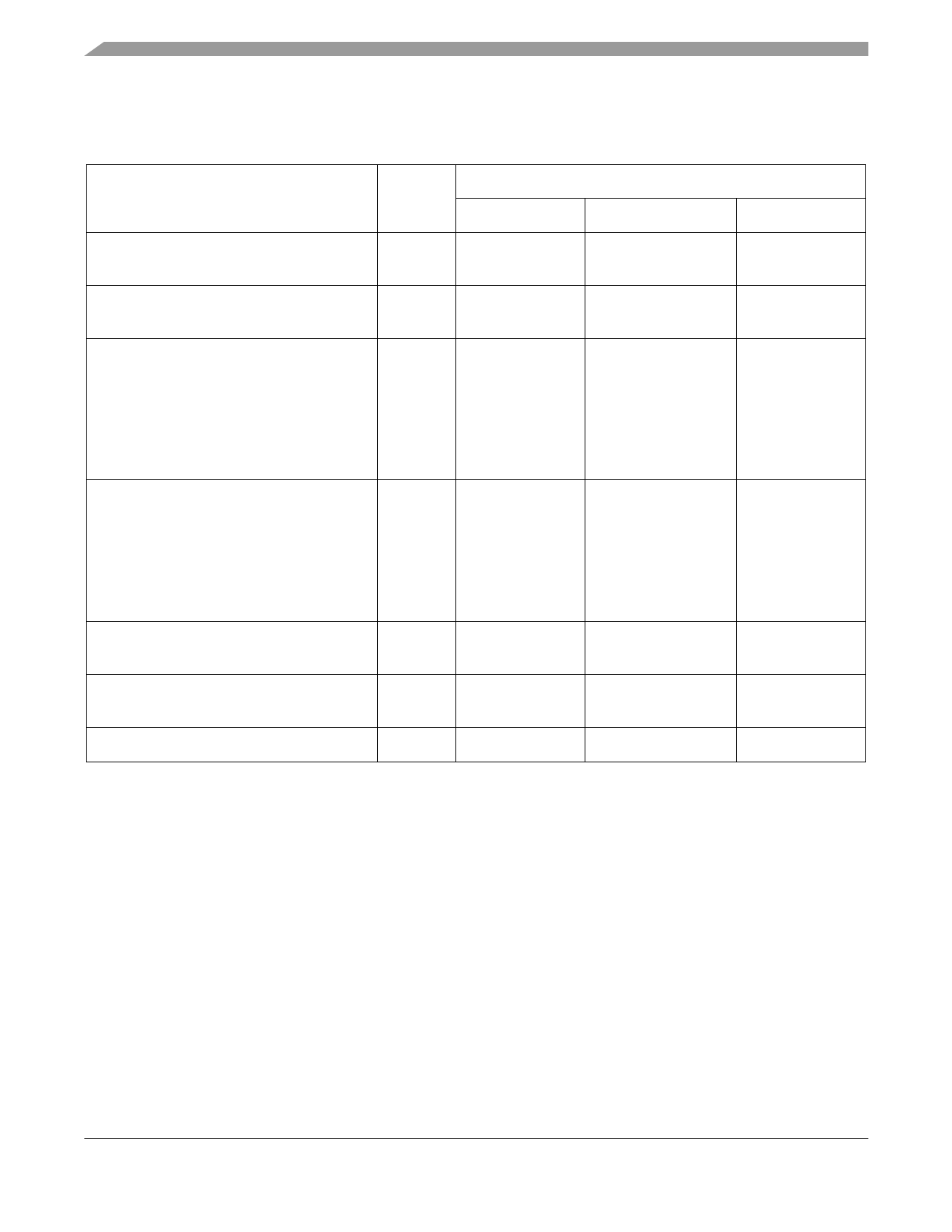
Internal Clocks
3.6 Internal Clocks
Table 3-4 Internal Clocks, CLKOUT
Characteristics
Symbol
Min
Expression1, 2
Typ
Max
Internal operation frequency and CLKOUT
f
with PLL enabled
—
(Ef × MF)/(PDF × DF)
—
Internal operation frequency and CLKOUT
f
—
Ef/2
—
with PLL disabled
Internal clock and CLKOUT high period
• With PLL disabled
• With PLL enabled and MF ≤ 4
• With PLL enabled and MF > 4
TH
—
0.49 × ETC × PDF ×
DF/MF
0.47 × ETC × PDF ×
DF/MF
ETC
—
—
0.51 × ETC × PDF ×
DF/MF
—
0.53 × ETC × PDF ×
DF/MF
Internal clock and CLKOUT low period
• With PLL disabled
• With PLL enabled and MF ≤ 4
• With PLL enabled and MF > 4
TL
—
0.49 × ETC × PDF ×
DF/MF
0.47 × ETC × PDF ×
DF/MF
ETC
—
—
0.51 × ETC × PDF ×
DF/MF
—
0.53 × ETC × PDF ×
DF/MF
Internal clock and CLKOUT cycle time with
TC
PLL enabled
—
ETC × PDF × DF/MF
—
Internal clock and CLKOUT cycle time with
TC
—
2 × ETC
—
PLL disabled
Instruction cycle time
ICYC
—
TC
—
1 DF = Division Factor
Ef = External frequency
ETC = External clock cycle
MF = Multiplication Factor
PDF = Predivision Factor
TC = internal clock cycle
2 See the PLL and Clock Generation section in the DSP56300 Family Manual for a detailed discussion of the PLL.
DSP56362 Technical Data, Rev. 4
3-4
Freescale Semiconductor
Share Link: 