MP7680 View Datasheet(PDF) - Exar Corporation
Part Name
Description
Manufacturer
MP7680 Datasheet PDF : 12 Pages
| |||
MP7680
DB11-DB4
(MSB)
DB3-DB0
(LSB)
DB11-
DB8
0
MUX
1
B1/B2
Disable-B1
A1 (MSB)
A0 (LSB)
CS
WR1
Latch
Address
Decoder
Enable A
Enable B
Enable C
Enable D
INPUT LA TCHES
DAC LA TCHES
8
LA11 - LA0
8
D B1 Q
E Latch
D
DA11 - DA0
12
Q
DAC
4
D
E
B2
Latch
Q
4
E
8
D B1
8
Q
E Latch
DB11 - DB0
12
D
Q
DAC
4
D
E
B2
Latch
Q
4
E
8
8
D B1 Q
E Latch
DC11 - DC0
12
D
Q
DAC
4
D
E
B2
Latch
Q
4
E
8
8
D B1 Q
E Latch
DD11 - DD0
12
D
Q
DAC
4
D
E
B2
Latch
Q
4
E
Transfer
XFER WR2
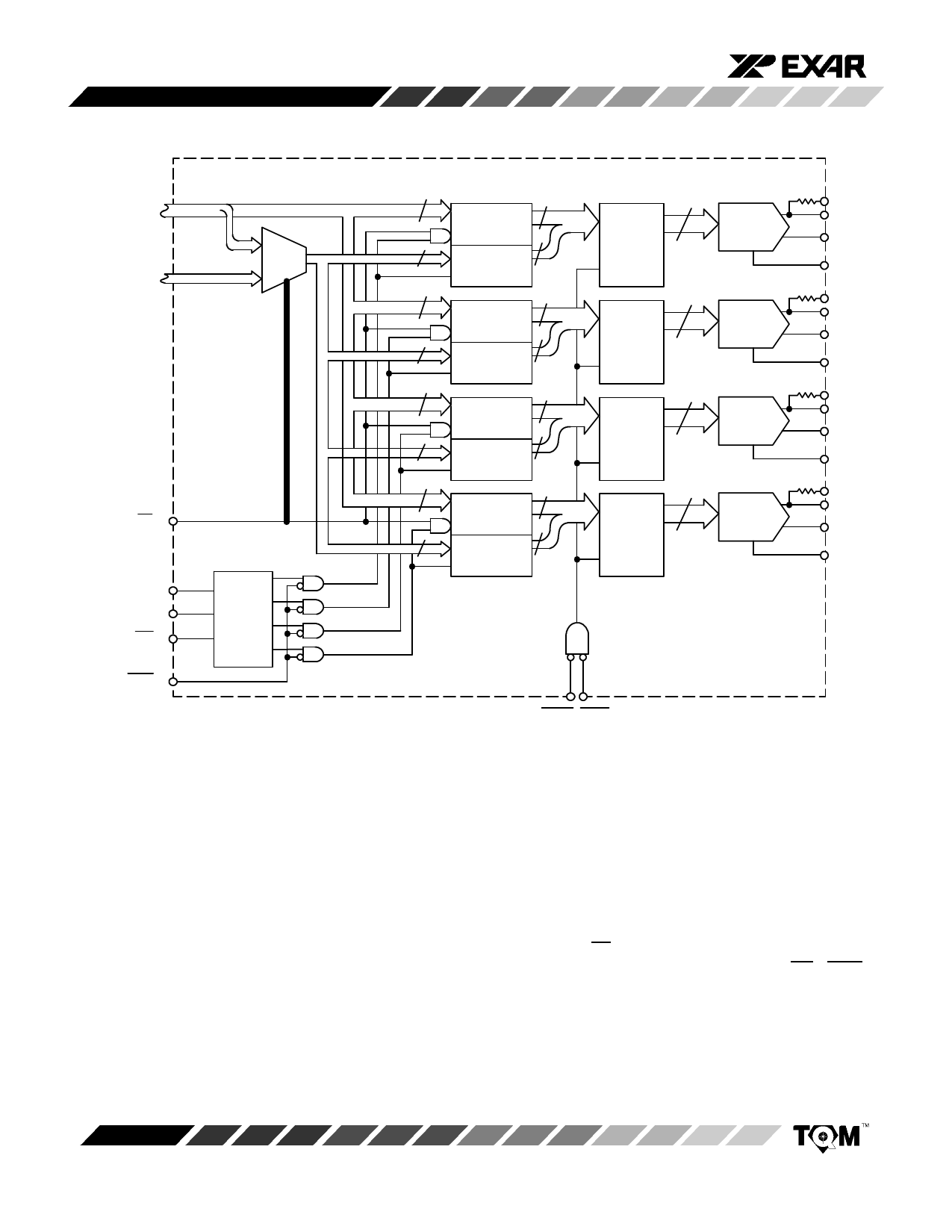
Figure 3. Latches Control Logic
RFBA
IOUT1A
IOUT2A
VREFA
RFBB
IOUT1B
IOUT2B
VREFB
RFBC
IOUT1C
IOUT2C
VREFC
RFBD
IOUT1D
IOUT2D
VREFD
THEOR Y OF OPERA TION
Digital Interface
W riting to Input Latches
Figure 3. shows the internal control logic. The logic that
controls the writing of the input latches and the one that
controls the DAC latches are completely separated. It is
easy to understand how the MP7680/80A works by
understanding each basic operation.
By keeping B1/B2 = high, a 12-bit bus has direct access to
the 12 bits of the input latches. The condition CS = WR1 =
0 loads the values contained in the data bus DB11-DB0
into the input latch addresses by A1, A0 (Figure 4. ,
Table 1. ).
Rev. 3.10
8
Share Link: 