NJU6538 View Datasheet(PDF) - Japan Radio Corporation
Part Name
Description
Manufacturer
NJU6538 Datasheet PDF : 27 Pages
| |||
NJU6538
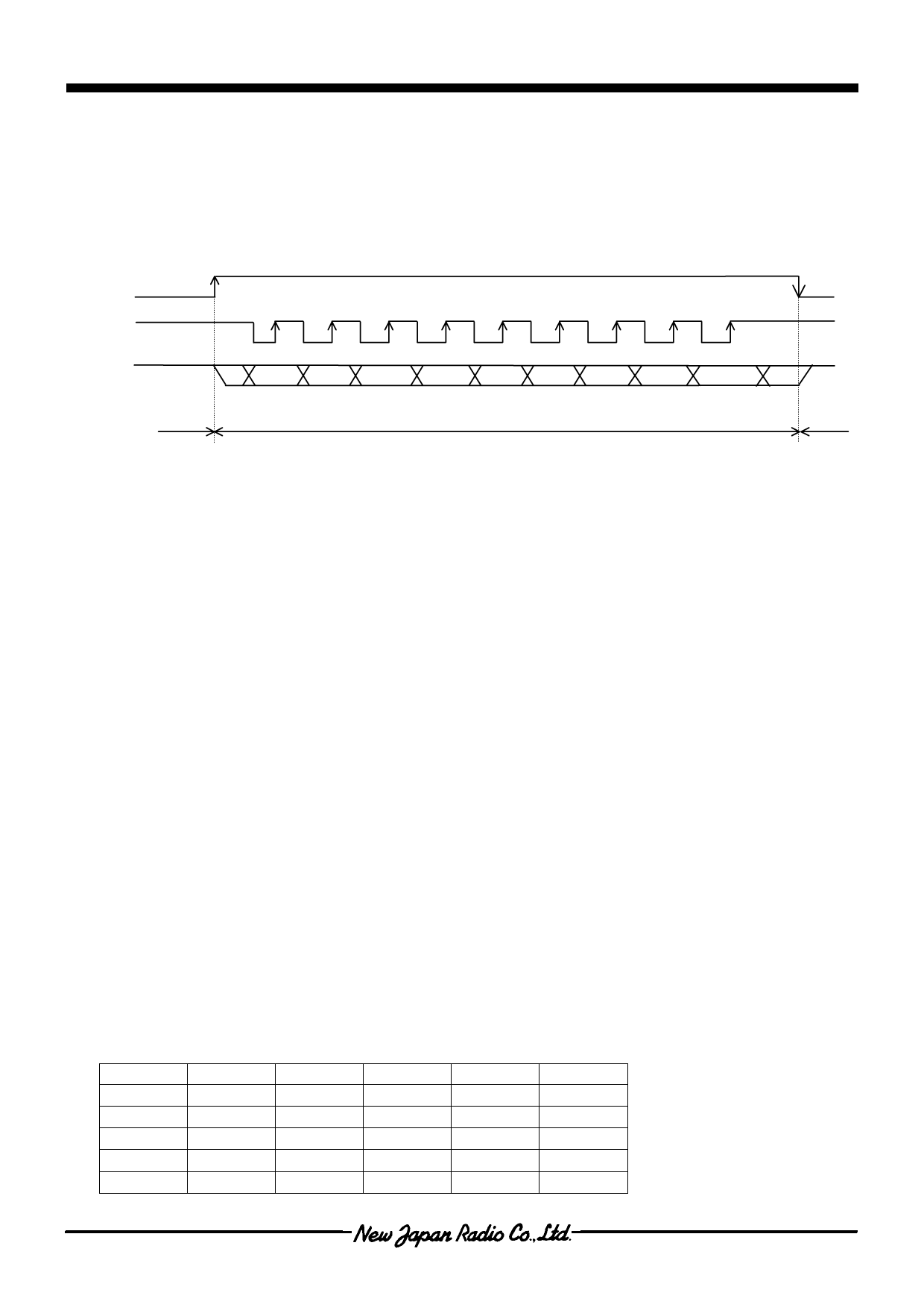
(3) Input Data Format and Timing
Data format is shown below.
When the CE terminal goes to “L”, I/F is data output.
When the CE terminal goes to “H” (rising edge) at SCL terminal “H”, I/F is data input.
CE
SCL
SIO
* D7 D6 D5 D4 D3 D2 D1 D0 A0
SIO state Output
Input
*
Output
NOTE1) Data fetched at SCL rising edge.
NOTE2) A contents change of the instruction and data which were written is fetched by the 9th rising edge of
SCL.
NOTE3) When the instruction and data which were written are less than 9-bit, they are ignored and is not fetched.
NOTE4) When the instruction and data which were written are over 9-bit, the last 9-bit is valid.
(4) Power save mode set
Power save mode is set by “Power save mode set” instruction. The segment and common output "L" is
outputted, the OSC terminal halts an oscillation (it oscillates at the time of key-on), and consumption current
is decreased.
Power save mode is canceled, when normally set by "Power save mode set" instruction.
(5) Key scan circuit
Key scan circuit connects the 5 x 5 key-matrix maximum and reads the data of 25 keys maximum. It
chooses the number of keys in key-matrix by “General output port / key scan output select” instruction.
It outputs a identified key data to MPU after comparison with two data read from the key-matrix in twice for
reliable key operation. If those data are not identified, key data is not outputted. It outputs “L” signal through
“SO” terminal as the request after 332T[s] (T=1/fsys=2/fosc,fsys : Internal system clock frequency) when
any key is operated. Furthermore, the key scan circuit structures for reducing the external components like as
Diodes to prevent circuit short problem.
(5-1) The relation between output data and key matrix
The relation between output data and key matrix shows bellow table and sets “1” signal for operated
key.
In case of 20 keys application, unassigned area for keys from KD1 to KD5 in bellow table take “0”
signal.
In mode of Power save 1, area for keys from KD1 to KD20 in bellow table take “0” signal. In mode of
Power save 2, area from KD1 to KD15 take “0” signal also. The terminals, which are not connected any
keys, should be open.
K0
K1
K2
K3
K4
S0
KD1
KD2
KD3
KD4
KD5
S1
KD6
KD7
KD8
KD9
KD10
S2
KD11
KD12
KD13
KD14
KD15
S3
KD16
KD17
KD18
KD19
KD20
S4
KD21
KD22
KD23
KD24
KD25
- 14 -
Ver.2003-05-09
Share Link: 