SP506 View Datasheet(PDF) - Signal Processing Technologies
Part Name
Description
Manufacturer
SP506 Datasheet PDF : 30 Pages
| |||
SP506 and SP507 Drive Capability
According to the ITU-T V.11 standard, the maximum
cable length for a differential V.11 transmission is
4,000 feet (~1,000 meters). However, the standard
also illustrates a derating graph of data rate versus
cable length. So actually in a real application, the
system would not be able to transmit 10Mbps over
the full 4,000 feet of Category 3 or similar type cable.
As cable parasitics add up over longer cable lengths,
capacitance and other affects will degrade the signal,
especially at higher frequencies.
The signal integrity depends mainly on the driver
output strength or "drivability" and parasitic
capacitance on the cable. RS-232 cabling is typically
50pF per foot, where as a good twisted pair type
cable for X.21, RS-449, EIA-530, or V.35 will
typically be 10pF per foot or less. Some better quality
cables will have 3-5pF per foot.
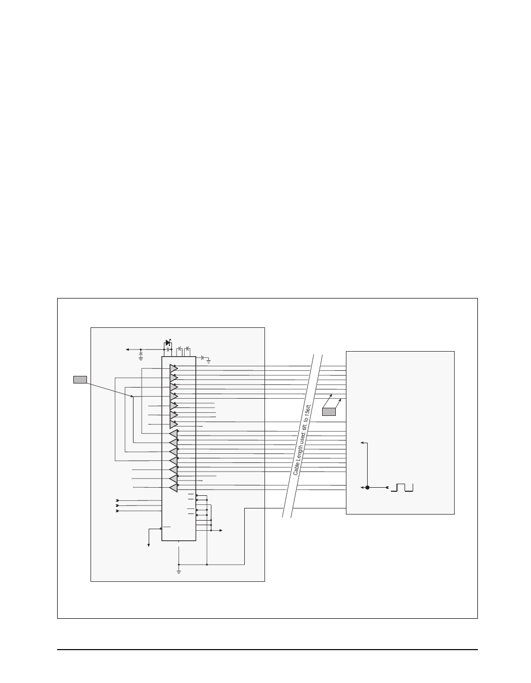
Using a typical setup with a TTC Fireberd 6000A Bit
Error Rate Tester (BERT) connected with our SP507
evaluation board as configured in Figure 8 below,
the driver output performance was characterized
over various cable lengths. The 6000A BERT
emulated the DCE, which provided the TXC clock
pulse from 1.544Mbps to 12Mbps. The clock waveform
was propagated through the serial cable to the SP507
evaluation board, which was configured as the DTE.
The clock signal was then "echoed" through the
TxCE (Transmit Clock Echo) driver across the cable
and back the BERT. The clock signal input to the
TxCE driver (CH3) and the differential driver output
are measured with a oscilloscope to observe driver
waveform integrity. The differential driver output
was measured at the other end of the cable (M1 =
A - B), as if the receiver would view the incoming
signal. The data stream was generated by the DCE
and was propagated through the SP507's RxC
receiver and TxCE driver. The BERT also records
the number of bit errors occurring during the infinite
1:1 data bit stream that is sent back through the cable.
CH3
DTE (Evaluation Board)
+5V
“0”
“0”
“1”
MBRS140T3
22µF 22µF
22µF
10µF
27 26 30 28 31 32 22µF
VCC VDD C1+ C1-C2+ C2- VSS
61
TxD
59
14
58
DTR
56
13
54
RTS
52
16
63
TxCE
65
15
42
ST
44
22
47
RL
45
17
51
LL
49
24
70
RxD
71
1
37
RxC
38
20
66
CTS
67
80
68
DSR
69
78
35
DCD
36
19
39
TM
40
21
76
SCT
77
79
2
RTEN
12 M0
11 M1
3
RREN
4
TMEN
10 M2
SCTEN 7
5
LLEN
18
SP507CF RLEN 6
TTEN
LATCH
8
STEN 23
+5V
GND
Various GND pins (Refer to SP507 Datasheet)
+5V
DCE (emulated)
RxD
DSR
CTS
RxC
M1
Fireberd 6000A
Network/BER Tester
TxD
TxC
RTS
DTR
DCD
TxC
Signal GND
Notes: V.35 Mode selected.
Open Driver Inputs
are default as HIGH.
Figure 8. SP507 Cable Length Versus Throughput Circuit Configuration
SP505/6/7APN/03
SP505, SP506, SP507 Application Note
11
© Copyright 2000 Sipex Corporation
Share Link: 