FAN5250 View Datasheet(PDF) - Fairchild Semiconductor
Part Name
Description
Manufacturer
FAN5250 Datasheet PDF : 17 Pages
| |||
FAN5250
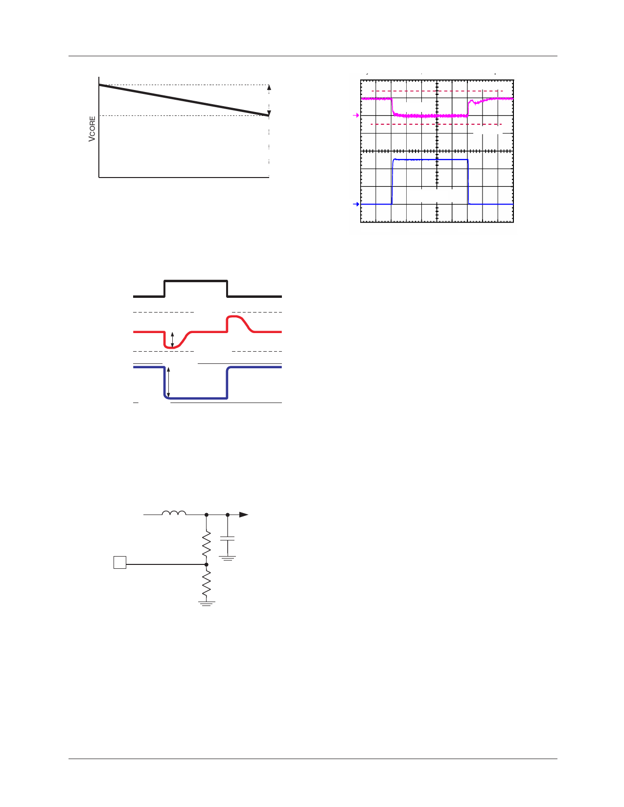
1.2
upper limit
VDROOP
VCPU = 1.35V
1
lower limit
ILOAD
IMAX
Figure 8. Active Droop
Additionally, the CPU power dissipation is also slightly
reduced as it is proportional to the applied voltage squared
and even slight voltage decrease translates to a measurable
reduction in power dissipated.
ILOAD
Vout
(no droop)
VESR
upper lim
Vout
droop » ESR
lower lim
upper lim
VESR
lower lim
Figure 9. Effect of Active Droop on ESR
The Crusoe processor regulation window including
transients is specified as +5%…–2%. To accommodate the
droop, the output voltage of the converter is raised by about
3.25% at no load as shown below (R24 = 1K and
R25 = 30.1K):
V CORE
R24
16 VCORE+
R25
COUT
Figure 10. Setting the No-Load Output Voltage Rise
The converter response to the load step is shown in Figure
11. At zero load current, the output voltage is raised ~50mV
above nominal value of 1.35V. When the load current
increases, the output voltage droops down approximately
55mV. Due to use of Active Droop, the converter’s output
voltage adaptively changes with the load current allowing
better utilization of the regulation window.
REV. 1.1.6 3/12/03
ICPU = 0A...5.0A
2
Ch1 50mV
Ch2 2.0A
M50µs
Figure 11. Converter Response to 5A Load Step
The current through RSENSE resistor (ISNS) is sampled
shortly after Q2 is turned on. That current is held, and then
injected (with a 1/48 gain) into the inverting path of the error
amp to produce an offset to the sensed output voltage at
VCORE + proportional to the load current.
VDROOP = 100K × -I-L---O-4---8A----D-×----×-R---R-S----ED---N-S---S(--O-E---N----)
(9a)
VDROOP = 2083 × -I-L---O----A---R-D----S-×--E--R--N---DS----ES---(--O----N----)
(9b)
Setting the Current Limit
A ratio of ISNS is also compared to the current established
when a 1.2 V internal reference drives the ILIM pin. The
threshold is determined at the point when the
I---S---8-N-----S-- > I---L---I--M--3-----×-----4-
Since
therefore,
ISNS = -I-L---O----A---R-D----S-×--E--R--N---DS----ES---(--O----N----)
ILIMIT = R-1---.-L-2--I-V-M-- × 43-- × -8----×-----(---1--R-0---0-D----S+---(--RO----N-S---)E---N----S----E----)
(10)
Since the tolerance on the current limit is largely dependent
on the ratio of the external resistors it is fairly accurate if the
voltage drop on the Switching Node side of RSENSE is an
accurate representation of the load current. When using the
MOSFET as the sensing element, the variation of RDS(ON)
causes proportional variation in the ISNS. This value not
only varies from device to device, but also has a typical
junction temperature coefficient of about 0.4%/°C
(consult the MOSFET datasheet for actual values), so the
actual current limit set point will decrease proportional to
increasing MOSFET die temperature. The same discussion
applies to the VDROOP calculation, which has an additional
initial error of ±20% due to its value being determined by
a ratio between RSENSE and the internal 100K resistor.
11
Share Link: 