UPD62A View Datasheet(PDF) - NEC => Renesas Technology
Part Name
Description
Manufacturer
UPD62A
NEC => Renesas Technology

UPD62A Datasheet PDF : 62 Pages
| |||
µPD62A
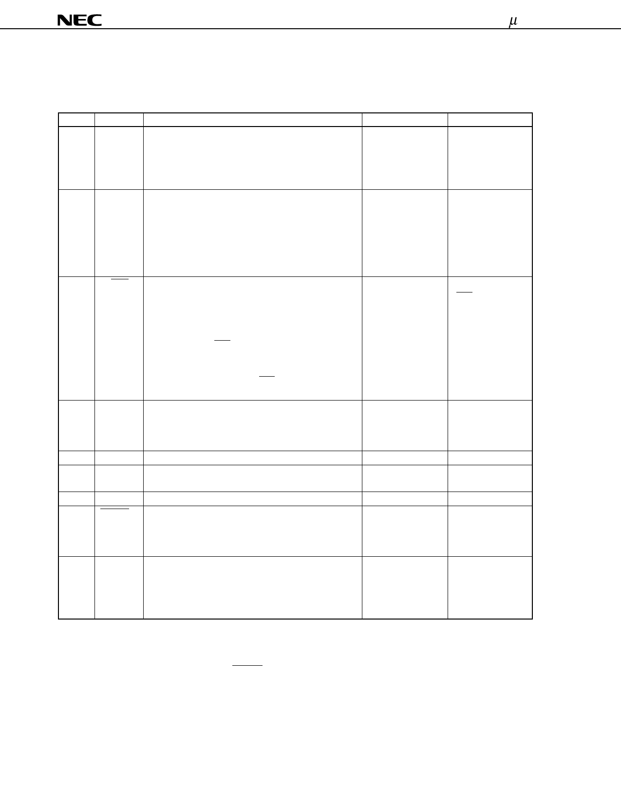
1. PIN FUNCTIONS
1.1 List of Pin Functions
Pin No.
1
2
15 to 20
3
4
5
6
7
8
9
10
11 to 14
Symbol
Function
KI/O0 to KI/O7 8-bit input/output port
Input/output can be specified in 8-bit units.
In input mode, a pull-down resistor is added.
In output mode, these pins can be used as the key scan
output of the key matrix.
S0
Input port
Can also be used as the key return input of the key
matrix.
In input mode, the use of a pull-down resistor for the S0
and S1 ports can be specified by software in 2-bit units.
If input mode is canceled by software, this pin is placed
in OFF mode and enters the high-impedance state.
S1/LED
Input/output port
In input mode (S1), this pin can also be used as the key
return input of the key matrix.
The use of a pull-down resistor for the S0 and S1 ports
can be specified by software in 2-bit units.
In output mode (LED), it becomes the remote control
transmission display output (active low). When the
remote control carrier is output from the REM output, this
pin outputs a low level from the LED output synchronously
with the REM signal.
REM
Infrared remote control transmission output.
The output is active high.
Carrier frequency: fX/8, fX/64, fX/96, high-level, fX/16,
fX/128, fX/192 (software supporting)
VDD
Power supply
XOUT
XIN
These pins are connected to system clock ceramic
resonators.
GND
Ground
RESET
Normally, this pin is the system reset input. By inputting
a low level, the CPU can be reset. When resetting with
the POC circuit (mask option) a low level is output. A
pull-up resistor is connected to this pin.
KI0 to KI3Note 2 4-bit input port
These pins can be used as the key return input of the key
matrix.
The use of a pull-down resistor can be specified by
software in 4-bit units.
After Format
CMOS
push-pullNote 1
—
CMOS push-pull
CMOS push-pull
—
—
—
—
—
After Reset
High-level output
High-impedance
(OFF mode)
High-level output
(LED)
Low-level output
—
Low level
(oscillation stopped)
—
—
Input (low-level)
Notes 1. Be aware that the drive capability of the low-level output side is held low.
2. In order to prevent malfunction, be sure to input a low level to more than one of pins KI0 to KI3 when
reset is released (when the RESET pin changes from low level to high level, or POC is released due
to supply voltage startup).
6
Data Sheet U14474EJ1V0DS00
Share Link: