ST7FLITEU05B3 View Datasheet(PDF) - STMicroelectronics
Part Name
Description
Manufacturer
ST7FLITEU05B3 Datasheet PDF : 115 Pages
| |||
ST7LITEU05 ST7LITEU09
FLASH PROGRAM MEMORY (Cont’d)
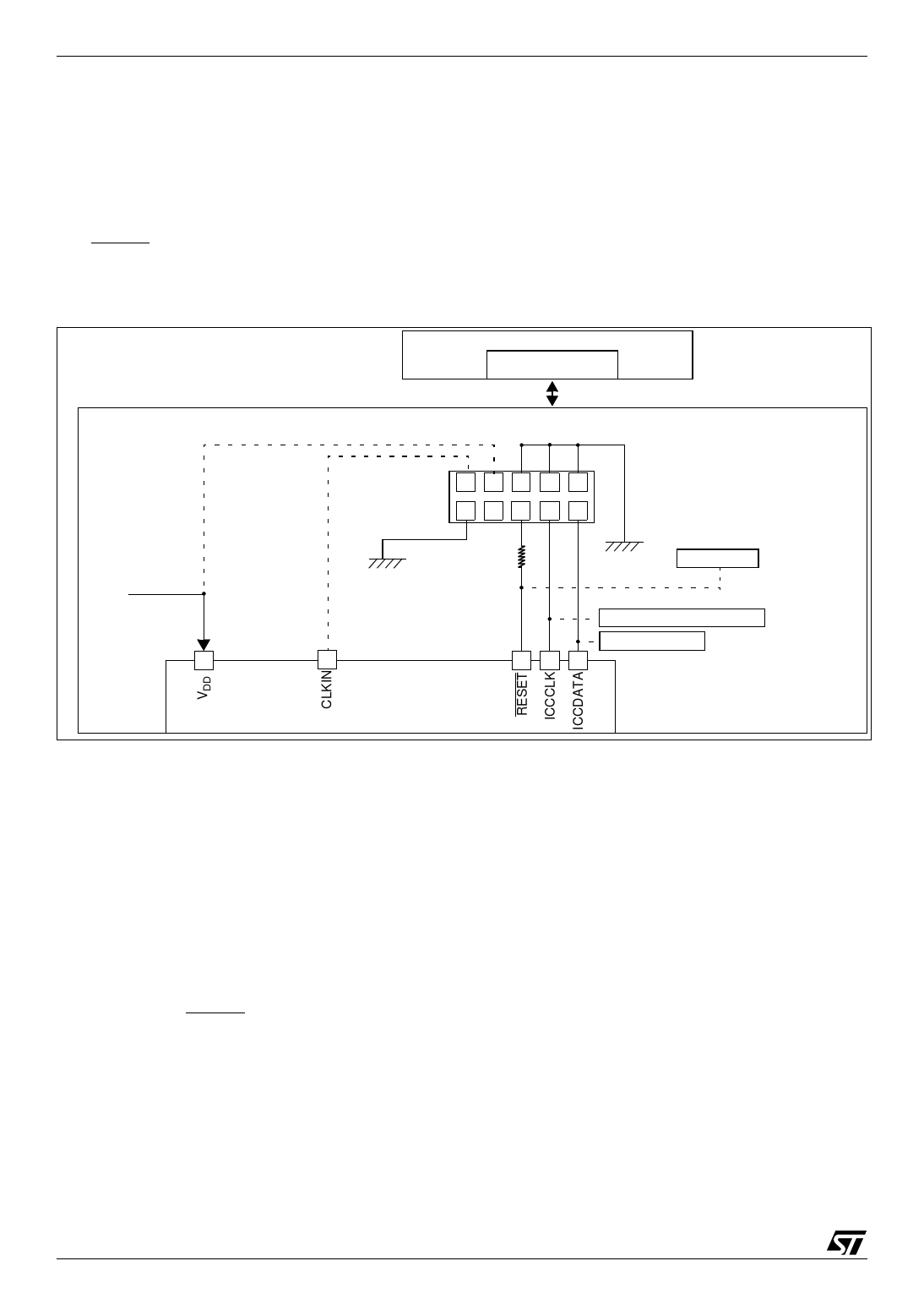
4.4 ICC interface
ICP needs a minimum of 4 and up to 6 pins to be
connected to the programming tool. These pins
are:
– RESET: device reset
– VSS: device power supply ground
– ICCCLK: ICC output serial clock pin (see note
1)
– ICCDATA: ICC input serial data pin
– CLKIN: main clock input for external source
–
NVDoDte:
application
3)
board
power
supply
(see
Figure 6. Typical ICC Interface
PROGRAMMING TOOL
ICC CONNECTOR
ICC Cable
(See Note 3)
ICC CONNECTOR
HE10 CONNECTOR TYPE
OPTIONAL
(See Note 4)
9 7 5 31
APPLICATION BOARD
10 8 6 4 2
3.3kΩ
(See Note 5)
APPLICATION
RESET SOURCE
See Note 2
APPLICATION
POWER SUPPLY
See Note 1 and Caution APPLICATION
See Note 1
I/O
ST7
Notes:
1. If the ICCCLK or ICCDATA pins are only used
as outputs in the application, no signal isolation is
necessary. As soon as the Programming Tool is
plugged to the board, even if an ICC session is not
in progress, the ICCCLK and ICCDATA pins are
not available for the application. If they are used as
inputs by the application, isolation such as a serial
resistor has to be implemented in case another de-
vice forces the signal. Refer to the Programming
Tool documentation for recommended resistor val-
ues.
2. During the ICP session, the programming tool
must control the RESET pin. This can lead to con-
flicts between the programming tool and the appli-
cation reset circuit if it drives more than 5mA at
high level (push pull output or pull-up resistor<1K).
A schottky diode can be used to isolate the appli-
cation RESET circuit in this case. When using a
classical RC network with R>1K or a reset man-
agement IC with open drain output and pull-up re-
sistor>1K, no additional components are needed.
In all cases the user must ensure that no external
reset is generated by the application during the
ICC session.
3. The use of Pin 7 of the ICC connector depends
on the Programming Tool architecture. This pin
must be connected when using most ST Program-
ming Tools (it is used to monitor the application
power supply). Please refer to the Programming
Tool manual.
4. Pin 9 has to be connected to the CLKIN pin of
the ST7 when ICC mode is selected with option
bytes disabled (35-pulse ICC entry mode). When
option bytes are enabled (38-pulse ICC entry
mode), the internal RC clock is forced, regardless
of the selection in the option byte.
12/115
1
Share Link: 