S25FL127SABMHI003(2005) View Datasheet(PDF) - Cypress Semiconductor
Part Name
Description
Manufacturer
S25FL127SABMHI003 Datasheet PDF : 131 Pages
| |||
S25FL127S
5.2.1
Capacitance Characteristics
Table 5.2 Capacitance
Parameter
Test Conditions
Min
Max
Unit
CIN
COUT
Input Capacitance (applies to SCK, CS#, RESET#)
Output Capacitance (applies to All I/O)
1 MHz
1 MHz
8
pF
8
pF
Note:
1. Parameter values are not 100% tested. For more information on capacitance, please consult the IBIS models.
5.3 Reset
5.3.1
Power-On (Cold) Reset
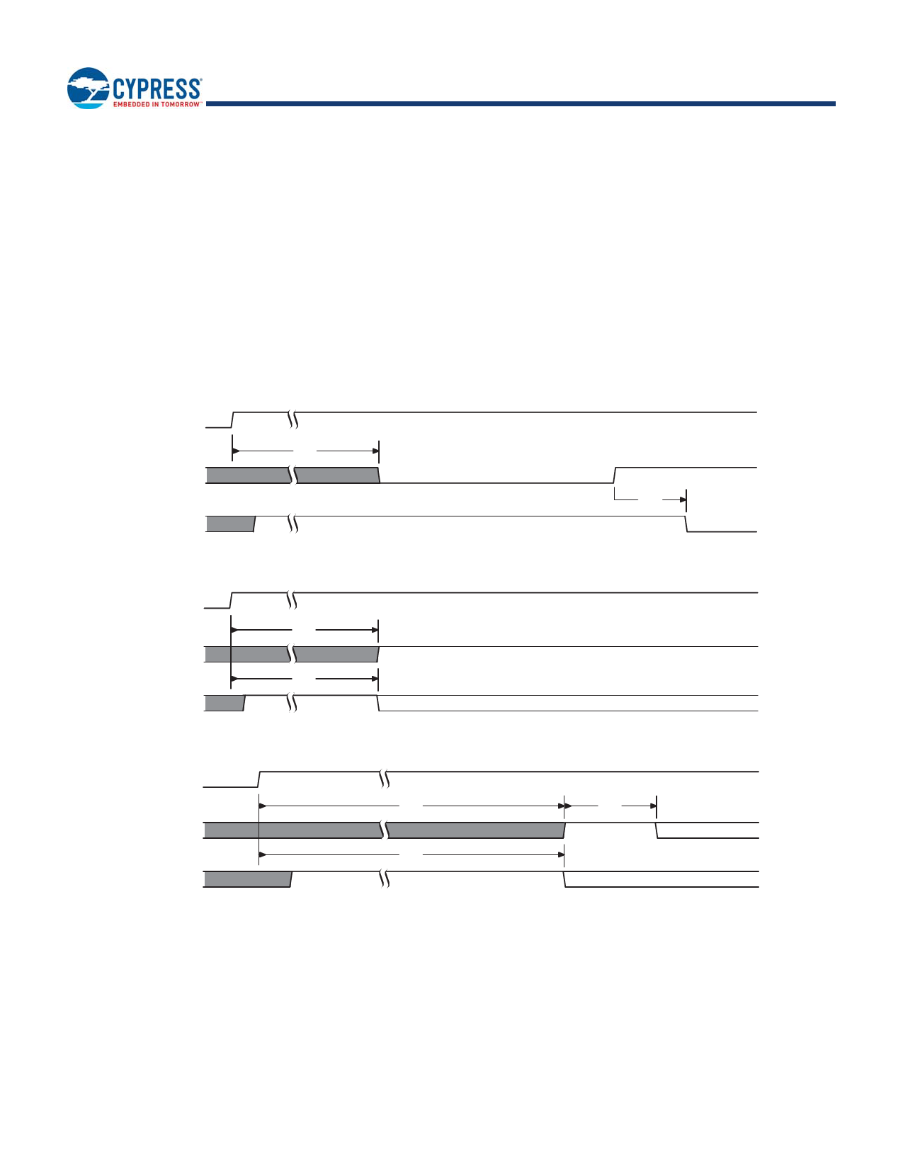
The device executes a Power-On Reset (POR) process until a time delay of tPU has elapsed after the moment that VCC rises above
the minimum VCC threshold. See Figure 4.3 on page 28, Table 4.2 on page 28, and Figure 5.4 on page 31. The device must not be
selected (CS# to go high with VCC) during power-up (tPU), i.e. no commands may be sent to the device until the end of tPU.
The IO3 / RESET# signal functions as the RESET# input when CS# is high for more than tRP time or when Quad Mode is not
enabled CR1V[1]=0.
RESET# is ignored during POR. If RESET# is low during POR and remains low through and beyond the end of tPU, CS# must
remain high until tRH after RESET# returns high. RESET# must return high for greater than tRS before returning low to initiate a
hardware reset.
VCC
RESET#
CS#
Figure 5.4 Reset Low at the End of POR
tPU
If RESET# is low at tPU end
tRH
CS# must be high at tPU end
VCC
RESET#
CS#
Figure 5.5 Reset High at the End of POR
tPU
If RESET# is high at tPU end
tPU
CS# may stay high or go low at tPU end
Document Number: 001-98282 Rev. *F
Page 31 of 130
Share Link: 