DSP56001 View Datasheet(PDF) - Motorola => Freescale
Part Name
Description
Manufacturer
DSP56001 Datasheet PDF : 64 Pages
| |||
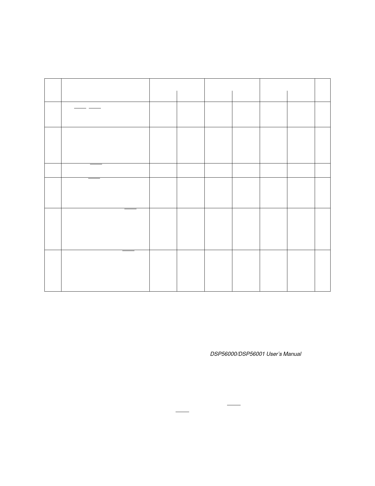
DSP56001 Electrical Characteristics
AC Electrical Characteristics - Reset, Stop, Mode Select, and Interrupt Timing
(Continued)
Num
Characteristics
20.5 MHz
27 MHz
33 MHz
Unit
Min
Max
Min
Max
Min
Max
23 Synchronous Interrupt Setup Time
from IRQA, IRQB Assertion to the
25
cyc-10
19
cyc-8
16
cyc-7
ns
Synchronous Rising Edge of External
Clock (see Notes 5, 6)
24 Synchronous Interrupt Delay Time
from the Synchronous Rising Edge of 13 cyc+ 13 cyc+ 13 cyc+ 13 cyc+ 13 cyc+ 13 cyc+ ns
External Clock to the First External
tc*h+8
tch* +30
tc*h+6
tch* +23
tc*h+5
tch* +19
Address Output Valid Caused by the
First Instruction Fetch after Coming out
of Wait State (see Notes 3, 5)
25 Duration for IRQA Assertion to
Recover from Stop State (see Note 4)
25
—
19
—
16
—
ns
26 Delay from IRQA Assertion to Fetch of
First Instruction (for Stop) for
Internal Osc / OMR bit 6 = 0 65545 cyc
—
65545 cyc
—
65545 cyc
—
ns
External Clock / OMR bit 6 = 1 17 c*yc
—
17 c*yc
—
17 c*yc
—
ns
(see Notes 1, 2, and 7)
*
*
*
27 Duration for Level Sensitive IRQA
Assertion to Fetch of First Interrupt
Instruction (for Stop) for
Internal Osc / OMR bit 6 = 0 65533 cyc
—
65533 cyc
—
65533 cyc
—
ns
+tc*l
+tc*l
+tc*l
External Clock / OMR bit 6 = 1 5 cyc+tcl
—
5 cyc+tcl
—
5 cyc+tcl
—
ns
(see Notes 1, 2, and 7)
*
*
*
28 Delay from Level Sensitive IRQA
Assertion to Fetch of First Interrupt
Instruction (for Stop) for
I nternal Osc / OMR bit 6 = 0 65545 cyc
—
65545 cyc
—
65545 cyc
—
ns
External Clock / OMR bit 6 = 1 17 c*yc
—
17 c*yc
—
17 c*yc
—
ns
(see Notes 1, 2, and 7)
*
*
*
Notes:
1. A clock stabilization delay is required when using the on-chip crystal oscillator in
two cases:
1) after power-on reset, and
2) when recovering from Stop mode.
During this stabilization period, T will not be constant. Since this stabilization period
varies, a delay of 150,000T is typically allowed to assure that the oscillator is stabilized
before executing programs. While it is possible to set OMR bit 6 = 1 when using
the internal crystal oscillator, it is not recommended and these specifications do not
guarantee timings for that case. See Section 8.5 in the DSP56000/DSP56001 User’s Manual for
additional information.
2. Circuit stabilization delay is required during reset when using an external clock in
two cases:
1) after power-on reset, and
2) when recovering from Stop mode.
3. For Revision B silicon, the min and max numbers are 12cyc+Tch+8 and 12cyc+Tch+30, respec-
tively.
4. The minimum is specified for the duration of an edge triggered IRQA interrupt required to recover
from the STOP state without having the IRQA interrupt accepted.
5. Timing #23 is for all IRQx interrupts while timing #24 is only when exiting WAIT.
6. Timing #23 triggers off T1 in the normal state and off T1/T3 when exiting the WAIT state.
7. The timings in the table are for Rev. C parts. The timings for Rev. C parts are shorter by 1 cyc than
the Rev. B parts when OMR6=0.
DSP56001
MOTOROLA
13
Share Link: 