DSP56311 View Datasheet(PDF) - Freescale Semiconductor
Part Name
Description
Manufacturer
DSP56311 Datasheet PDF : 96 Pages
| |||
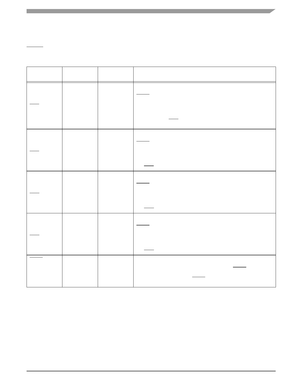
1.6 Interrupt and Mode Control
Interrupt and Mode Control
The interrupt and mode control signals select the chip operating mode as it comes out of hardware reset. After
RESET is deasserted, these inputs are hardware interrupt request lines.
Table 1-9. Interrupt and Mode Control
Signal Name
Type
MODA
Input
IRQA
Input
MODB
IRQB
MODC
IRQC
MODD
IRQD
RESET
Input
Input
Input
Input
Input
Input
Input
State During
Reset
Schmitt-trigger
Input
Signal Description
Mode Select A—MODA, MODB, MODC, and MODD select one of 16 initial
chip operating modes, latched into the Operating Mode Register when the
RESET signal is deasserted.
Schmitt-trigger
Input
External Interrupt Request A—After reset, this input becomes a level-
sensitive or negative-edge-triggered, maskable interrupt request input during
normal instruction processing. If the processor is in the STOP or WAIT
standby state and IRQA is asserted, the processor exits the STOP or WAIT
state.
Mode Select B—MODA, MODB, MODC, and MODD select one of 16 initial
chip operating modes, latched into the Operating Mode Register when the
RESET signal is deasserted.
Schmitt-trigger
Input
External Interrupt Request B—After reset, this input becomes a level-
sensitive or negative-edge-triggered, maskable interrupt request input during
normal instruction processing. If the processor is in the WAIT standby state
and IRQB is asserted, the processor exits the WAIT state.
Mode Select C—MODA, MODB, MODC, and MODD select one of 16 initial
chip operating modes, latched into the Operating Mode Register when the
RESET signal is deasserted.
Schmitt-trigger
Input
External Interrupt Request C—After reset, this input becomes a level-
sensitive or negative-edge-triggered, maskable interrupt request input during
normal instruction processing. If the processor is in the WAIT standby state
and IRQC is asserted, the processor exits the WAIT state.
Mode Select D—MODA, MODB, MODC, and MODD select one of 16 initial
chip operating modes, latched into the Operating Mode Register when the
RESET signal is deasserted.
Schmitt-trigger
Input
External Interrupt Request D—After reset, this input becomes a level-
sensitive or negative-edge-triggered, maskable interrupt request input during
normal instruction processing. If the processor is in the WAIT standby state
and IRQD is asserted, the processor exits the WAIT state.
Reset—Places the chip in the Reset state and resets the internal phase
generator. The Schmitt-trigger input allows a slowly rising input (such as a
capacitor charging) to reset the chip reliably. When the RESET signal is
deasserted, the initial chip operating mode is latched from the MODA, MODB,
MODC, and MODD inputs. The RESET signal must be asserted after
powerup.
DSP56311 Technical Data, Rev. 8
Freescale Semiconductor
1-7
Share Link: 