DSP56311 View Datasheet(PDF) - Freescale Semiconductor
Part Name
Description
Manufacturer
DSP56311 Datasheet PDF : 96 Pages
| |||
AC Electrical Characteristics
2.4.2 External Clock Operation
The DSP56311 system clock is derived from the on-chip oscillator or is externally supplied. To use the on-chip
oscillator, connect a crystal and associated resistor/capacitor components to EXTAL and XTAL; examples are
shown in Figure 2-1.
EXTAL
XTAL
R
C
XTAL1
C
Fundamental Frequency
Crystal Oscillator
Note: Make sure that in
the PCTL Register:
• XTLD (bit 16) = 0
• If fOSC > 200 kHz,
XTLR (bit 15) = 0
Suggested Component Values:
fOSC = 4 MHz
R = 680 kΩ ± 10%
C = 56 pF ± 20%
fOSC = 20 MHz
R = 680 kΩ ± 10%
C = 22 pF ± 20%
Calculations were done for a 4/20 MHz crystal
with the following parameters:
• CLof 30/20 pF,
• C0 of 7/6 pF,
• series resistance of 100/20 Ω, and
• drive level of 2 mW.
Figure 2-1. Crystal Oscillator Circuits
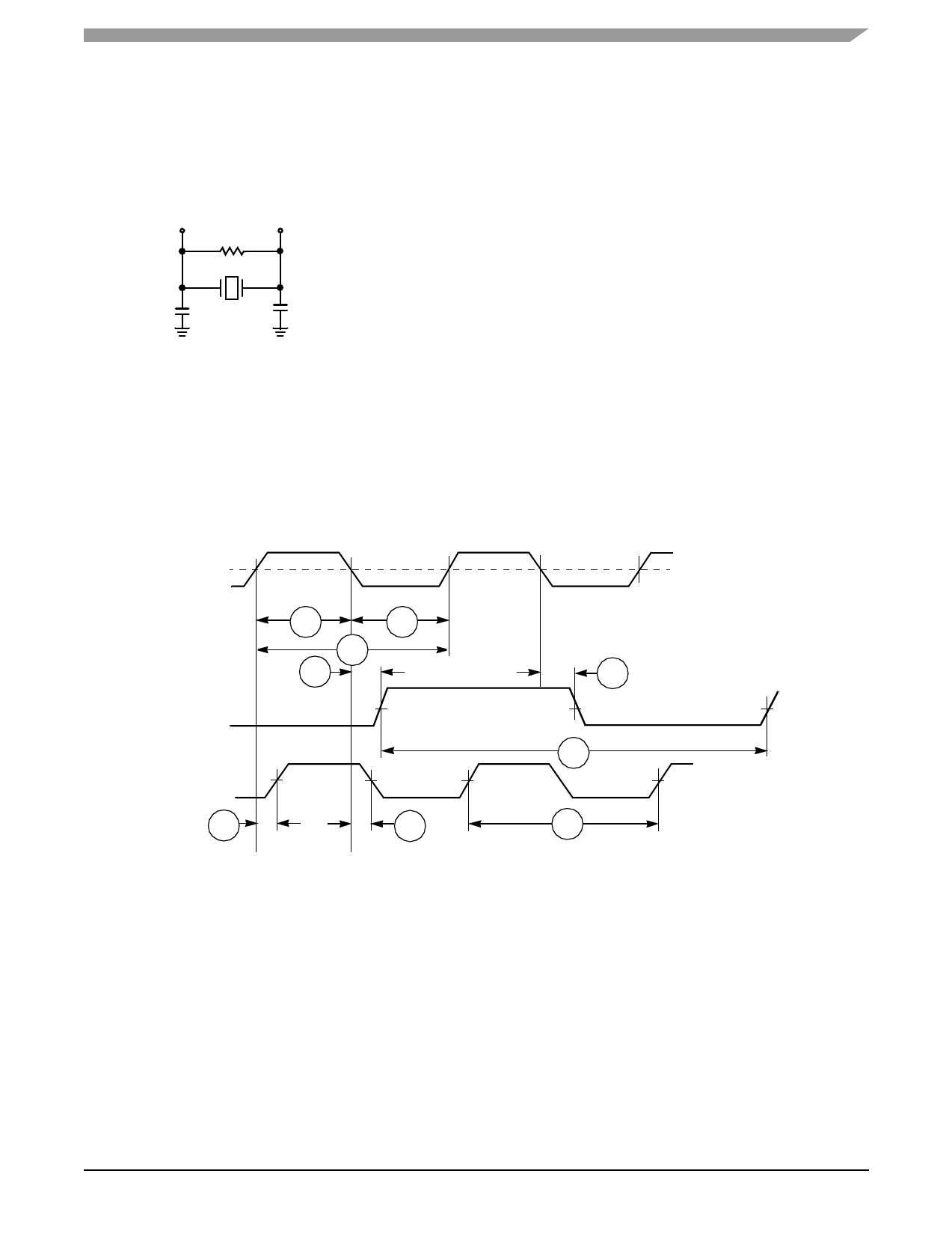
If an externally-supplied square wave voltage source is used, disable the internal oscillator circuit during bootup by
setting XTLD (PCTL Register bit 16 = 1—see the DSP56311 User’s Manual). The external square wave source
connects to EXTAL; XTAL is not physically connected to the board or socket. Figure 2-2 shows the relationship
between the EXTAL input and the internal clock and CLKOUT.
EXTAL
Midpoint
VIHX
VILX ETH
2
5
CLKOUT with
PLL disabled
ETL
3
4
ETC
Note:
The midpoint is
0.5 (VIHX + VILX).
5
7
CLKOUT with
PLL enabled
6a
6b
7
Figure 2-2. External Clock Timing
DSP56311 Technical Data, Rev. 8
Freescale Semiconductor
2-5
Share Link: 