DSP56362 View Datasheet(PDF) - Freescale Semiconductor
Part Name
Description
Manufacturer
DSP56362 Datasheet PDF : 152 Pages
| |||
Interrupt and Mode Control
2.6 Interrupt and Mode Control
The interrupt and mode control signals select the chip’s operating mode as it comes out of hardware reset.
After RESET is deasserted, these inputs are hardware interrupt request lines.
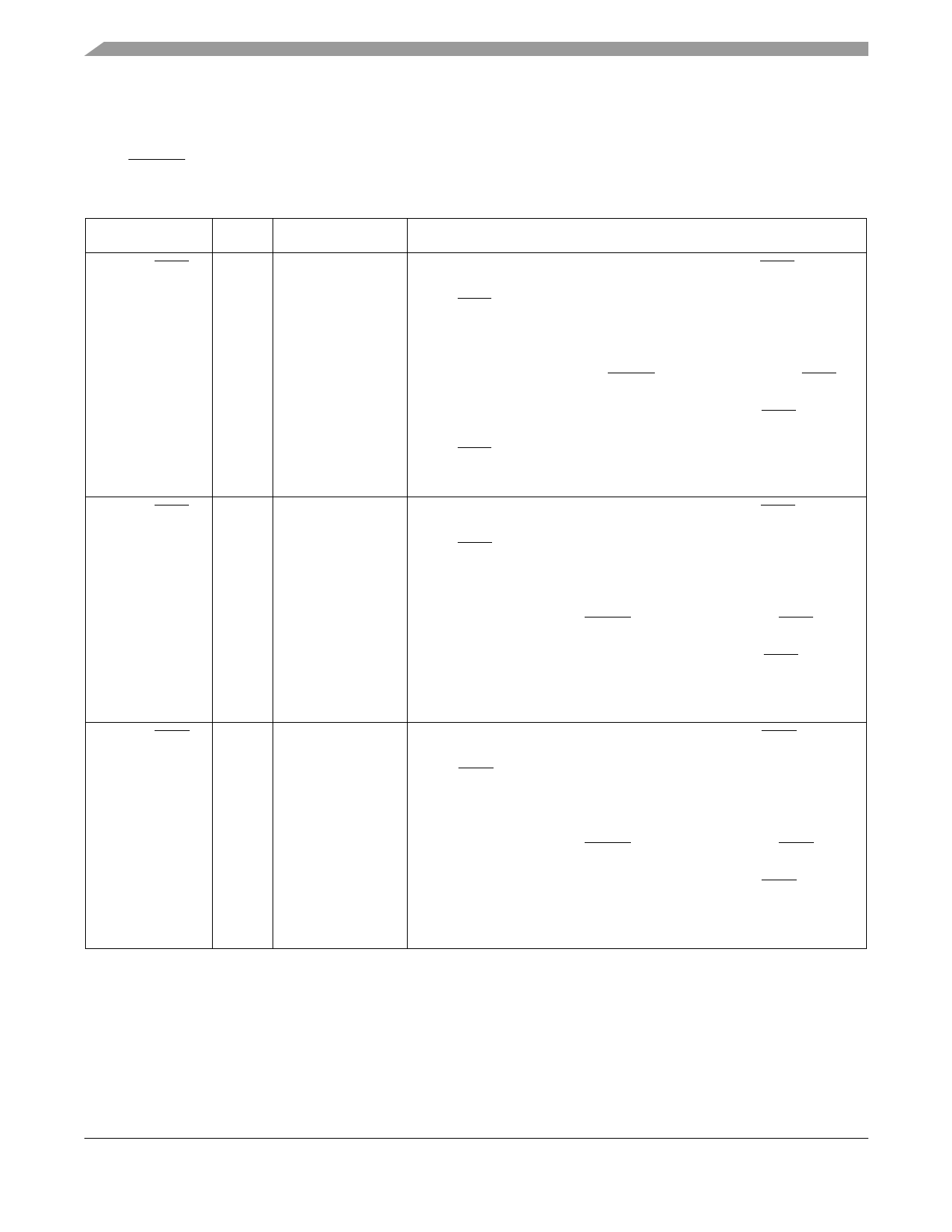
Table 2-8 Interrupt and Mode Control
Signal Name Type State during Reset
Signal Description
MODA/IRQA
Input
Input
Mode Select A/External Interrupt Request A—MODA/IRQA is an
active-low Schmitt-trigger input, internally synchronized to the DSP clock.
MODA/IRQA selects the initial chip operating mode during hardware reset
and becomes a level-sensitive or negative-edge-triggered, maskable
interrupt request input during normal instruction processing. MODA,
MODB, MODC, and MODD select one of 16 initial chip operating modes,
latched into the OMR when the RESET signal is deasserted. If IRQA is
asserted synchronous to CLKOUT, multiple processors can be
resynchronized using the WAIT instruction and asserting IRQA to exit the
wait state. If the processor is in the stop standby state and the
MODA/IRQA pin is pulled to GND, the processor will exit the stop state.
This input is 5 V tolerant.
MODB/IRQB
Input
Input
Mode Select B/External Interrupt Request B—MODB/IRQB is an
active-low Schmitt-trigger input, internally synchronized to the DSP clock.
MODB/IRQB selects the initial chip operating mode during hardware reset
and becomes a level-sensitive or negative-edge-triggered, maskable
interrupt request input during normal instruction processing. MODA,
MODB, MODC, and MODD select one of 16 initial chip operating modes,
latched into OMR when the RESET signal is deasserted. If IRQB is
asserted synchronous to CLKOUT, multiple processors can be
re-synchronized using the WAIT instruction and asserting IRQB to exit the
wait state.
This input is 5 V tolerant.
MODC/IRQC
Input
Input
Mode Select C/External Interrupt Request C—MODC/IRQC is an
active-low Schmitt-trigger input, internally synchronized to the DSP clock.
MODC/IRQC selects the initial chip operating mode during hardware reset
and becomes a level-sensitive or negative-edge-triggered, maskable
interrupt request input during normal instruction processing. MODA,
MODB, MODC, and MODD select one of 16 initial chip operating modes,
latched into OMR when the RESET signal is deasserted. If IRQC is
asserted synchronous to CLKOUT, multiple processors can be
resynchronized using the WAIT instruction and asserting IRQC to exit the
wait state.
This input is 5 V tolerant.
DSP56362 Technical Data, Rev. 4
2-8
Freescale Semiconductor
Share Link: 