DSP56367P View Datasheet(PDF) - Freescale Semiconductor
Part Name
Description
Manufacturer
DSP56367P Datasheet PDF : 100 Pages
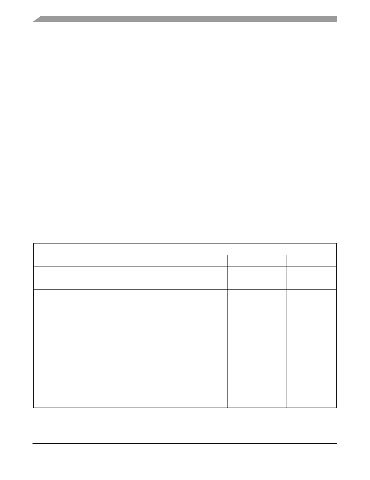
| |||
AC Electrical Characteristics
3 This characteristic does not apply to PCAP.
4 The Appendix A, "Power Consumption Benchmark" section provides a formula to compute the estimated current
requirements in Normal mode. In order to obtain these results, all inputs must be terminated (i.e., not allowed to float).
Measurements are based on synthetic intensive DSP benchmarks. The power consumption numbers in this specification are
90% of the measured results of this benchmark. This reflects typical DSP applications. Typical internal supply current is
measured with VCCQL = 1.8V, VCC(other) = 3.3V at TJ = 25°C. Maximum internal supply current is measured with VCCQL = 1.89V,
VCC(other) = 3.46V at TJ = 95°C.
5 In order to obtain these results, all inputs, which are not disconnected at Stop mode, must be terminated (i.e., not allowed to
float).
6 Periodically sampled and not 100% tested
3.5 AC Electrical Characteristics
The timing waveforms shown in the AC electrical characteristics section are tested with a VIL maximum
of 0.4 V and a VIH minimum of 2.4 V for all pins except EXTAL. AC timing specifications, which are
referenced to a device input signal, are measured in production with respect to the 50% point of the
respective input signal’s transition. DSP56367 output levels are measured with the production test machine
VOL and VOH reference levels set at 0.4 V and 2.4 V, respectively.
NOTE
Although the minimum value for the frequency of EXTAL is 0 MHz, the
device AC test conditions are 15 MHz and rated speed.
3.6 Internal Clocks
Table 3-4 Internal Clocks
Characteristics
Symbol
Min
Expression1, 2
Typ
Max
Internal operation frequency with PLL enabled
f
—
(Ef × MF)/(PDF × DF)
—
Internal operation frequency with PLL disabled
f
—
Ef/2
—
Internal clock high period
• With PLL disabled
• With PLL enabled and MF ≤ 4
• With PLL enabled and MF > 4
TH
—
0.49 × ETC × PDF ×
DF/MF
0.47 × ETC × PDF ×
DF/MF
ETC
—
—
0.51 × ETC × PDF ×
DF/MF
—
0.53 × ETC × PDF ×
DF/MF
Internal clock low period
• With PLL disabled
• With PLL enabled and MF ≤ 4
• With PLL enabled and MF > 4
TL
—
0.49 × ETC × PDF ×
DF/MF
0.47 × ETC × PDF ×
DF/MF
ETC
—
—
0.51 × ETC × PDF ×
DF/MF
—
0.53 × ETC × PDF ×
DF/MF
Internal clock cycle time with PLL enabled
TC
—
ETC × PDF × DF/MF
—
DSP56367 Technical Data, Rev. 2.1
3-4
Freescale Semiconductor
Share Link: 