NJU6538 View Datasheet(PDF) - Japan Radio Corporation
Part Name
Description
Manufacturer
NJU6538 Datasheet PDF : 27 Pages
| |||
NJU6538
(m) General output port set.
This instruction sets the PWM value outputted from Po0 ~ Po3 terminals. The “General output
port select” instruction selects the general output port to output with PWM. The “General output port
PWM set” instruction sets the PWM value.
The “General output port select instruction" and the “General output port PWM set instruction" is
not necessary to continuously perform. Because these instructions are independently.
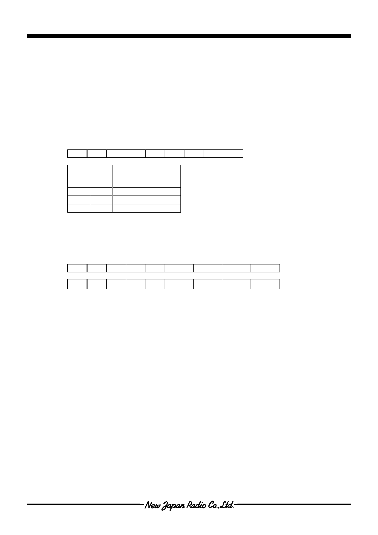
1. General output port select.
This instruction selects the general output port to output with PWM.
A0 D7 D6 D5 D4 D3 D2 D1 D0
0011000
Port
D1
D0
Port
0
0
Po0
0
1
Po1
1
0
Po2
1
1
Po3
2. General output port PWM set
This instruction sets the PWM value outputted from Po0 ~ Po3 terminals.
The PWM output setting is available for 128-step at each port output terminals.
A0 D7 D6 D5 D4
D3
D2
D1
D0
0
1
0
0
0 PWMEN PWM6 PWM5 PWM4
0
0
1
1
1
PWM3 PWM2 PWM1 PWM0
A) PWMEN
0:Selected general output port is ”L” output.
1:Selected general output port outputs PWM depending on PWM data.
B) PWM6 to PWM0
PWM value:This register sets the duty value of PWM outputted from the selected general output port.
The PWM value set requires twice, which are upper 3-bit and lower 4-bit.
The PWM duty is (Register + 1 ) / 128.
Ver.2003-05-09
- 11 -
Share Link: 