SST25VF040B View Datasheet(PDF) - Silicon Storage Technology
Part Name
Description
Manufacturer
SST25VF040B Datasheet PDF : 33 Pages
| |||
4 Mbit SPI Serial Flash
SST25VF040B
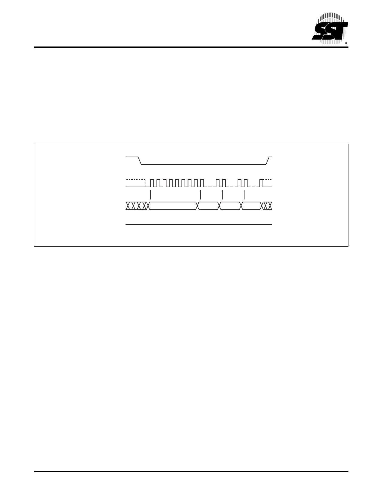
4-KByte Sector-Erase
The Sector-Erase instruction clears all bits in the selected 4
KByte sector to FFH. A Sector-Erase instruction applied to
a protected memory area will be ignored. Prior to any Write
operation, the Write-Enable (WREN) instruction must be
executed. CE# must remain active low for the duration of
any command sequence. The Sector-Erase instruction is
initiated by executing an 8-bit command, 20H, followed by
address bits [A23-A0]. Address bits [AMS-A12] (AMS = Most
Data Sheet
Significant address) are used to determine the sector
address (SAX), remaining address bits can be VIL or VIH.
CE# must be driven high before the instruction is executed.
The user may poll the Busy bit in the software status regis-
ter or wait TSE for the completion of the internal self-timed
Sector-Erase cycle. See Figure 12 for the Sector-Erase
sequence.
CE#
MODE 3
SCK MODE 0
0 1 2345 6 78
15 16
23 24 31
SI
20
ADD. ADD. ADD.
MSB
MSB
SO
HIGH IMPEDANCE
1295 SecErase.0
FIGURE 12: Sector-Erase Sequence
©2009 Silicon Storage Technology, Inc.
15
S71295-05-000
10/09
Share Link: 