TC642B View Datasheet(PDF) - Microchip Technology
Part Name
Description
Manufacturer
TC642B Datasheet PDF : 36 Pages
| |||
TC642B/TC647B
By modulating the voltage applied to the gate of the
MOSFET (QDRIVE), the voltage that is applied to the
fan is also modulated. When the VOUT pulse is high, the
gate of the MOSFET is turned on, pulling the voltage at
the drain of QDRIVE to zero volts. This places the full
12V across the fan for the ton period of the pulse. When
the duty cycle of the drive pulse is 100% (full on,
ton = t), the fan will run at full speed. As the duty cycle
is decreased (pulse on time “ton” is lowered), the fan
will slow down proportionally. With the TC642B and
TC647B devices, the duty cycle is controlled by either
the VIN or VMIN input, with the higher voltage setting the
duty cycle. This is described in more detail in Section
5.5, “Output Drive Device Selection”.
4.3 Fan Start-up
Often overlooked in fan speed control is the actual start-
up control period. When starting a fan from a non-oper-
ating condition (fan speed is zero revolutions per minute
(RPM)), the desired PWM duty cycle or average fan
voltage can not be applied immediately. Since the fan is
at a rest position, the fan’s inertia must be overcome to
get it started. The best way to accomplish this is to apply
the full rated voltage to the fan for a minimum of one
second. This will ensure that in all operating environ-
ments, the fan will start and operate properly. An exam-
ple of the start-up timing is shown in Figure 1-1.
A key feature of the TC642B/TC647B device is the
start-up timer. When power is first applied to the device,
(when the device is brought out of the shutdown mode
of operation) the VOUT output will go to a high state for
32 PWM cycles (one second for CF = 1 F). This will
drive the fan to full speed for this time-frame.
During the start-up period, the SENSE pin is being
monitored for fan pulses. If pulses are detected during
this period, the fan speed controller will then move to
PWM operation (see Section 4.5, “Minimum Fan
Speed”, for more details on operation when coming out
of start-up). If pulses are not detected during the start-
up period, the start-up timer is activated again. If pulses
are not detected at the SENSE pin during this addi-
tional start-up period, the FAULT output will go low to
indicate that a fan fault condition has occurred. See
Section 4.7, “FAULT Output”, for more details.
4.4 PWM Frequency & Duty Cycle Control
(CF & VIN Pins)
The frequency of the PWM pulse train is controlled by
the CF pin. By attaching a capacitor to the CF pin, the
frequency of the PWM pulse train can be set to the
desired value. The typical PWM frequency for a 1.0 F
capacitor is 30 Hz. The frequency can be adjusted by
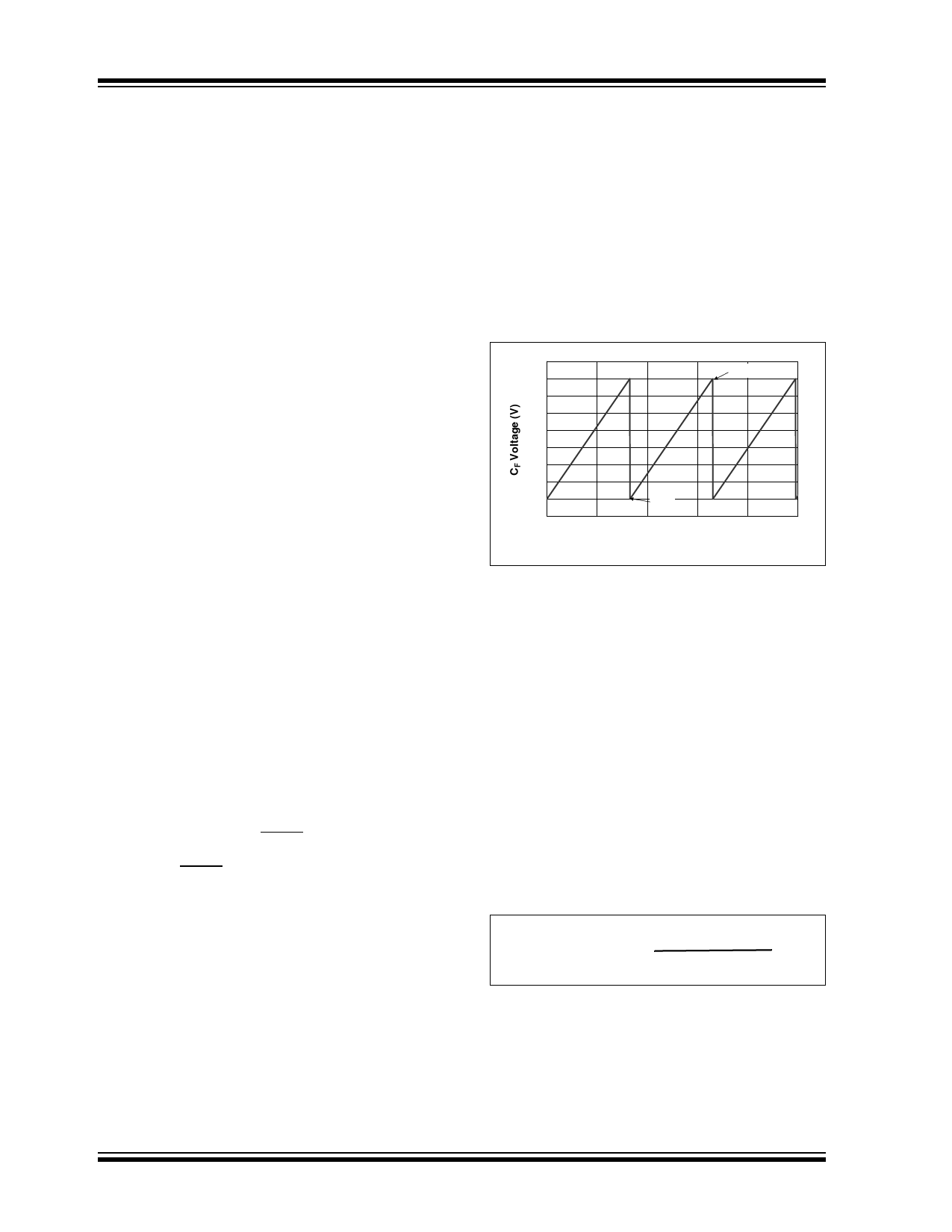
raising or lowering the value of the capacitor. The CF
pin functions as a ramp generator. The voltage at this
pin will ramp from 1.20V to 2.60V (typically) as a saw-
tooth waveform. An example of this is shown in
Figure 4-3.
2.8
CF = 1 µF
2.6
2.4
2.2
2.0
1.8
1.6
1.4
1.2
1.0
0
20
VCMAX
VCMIN
40
60
80
100
Time (msec)
FIGURE 4-3:
CF Pin Voltage.
The duty cycle of the PWM output is controlled by the
voltage at the VIN input pin (or the VMIN voltage, which-
ever is greater). The duty cycle of the PWM output is
produced by comparing the voltage at the VIN pin to the
voltage ramp at the CF pin. When the voltage at the VIN
pin is 1.20V, the duty cycle will be 0%. When the volt-
age at the VIN pin is 2.60V, the PWM duty cycle will be
100% (these are both typical values). The VIN to PWM
duty cycle relationship is shown in Figure 4-4.
The lower value of 1.20V is referred to as VCMIN and
the 2.60V threshold is referred to as VCMAX. A calcula-
tion for duty cycle is shown in the equation below. The
voltage range between VCMIN and VCMAX is character-
ized as VCSPAN and has a typical value of 1.4V with
minimum and maximum values of 1.3V and 1.5V,
respectively.
EQUATION
PWM DUTY CYCLE
Duty Cycle (%) = (VIN - VCMIN) * 100
VCMAX - VCMIN
DS21756C-page 12
2002-2013 Microchip Technology Inc.
Share Link: 