TC642B View Datasheet(PDF) - Microchip Technology
Part Name
Description
Manufacturer
TC642B Datasheet PDF : 36 Pages
| |||
.
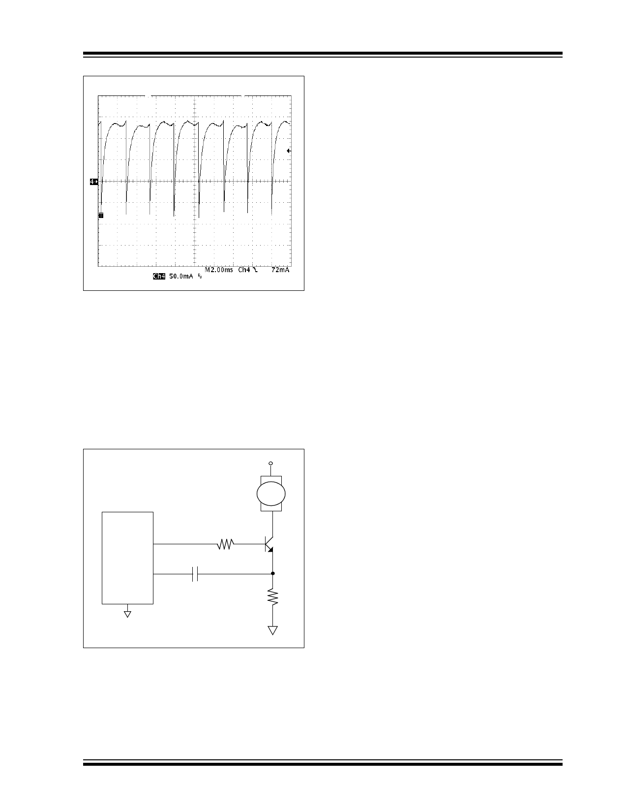
FIGURE 4-7:
Fan Current With
Commutation Pulses To Zero.
The SENSE pin senses positive voltage pulses that
have an amplitude of 70 mV (typical value). When a
pulse is detected, the missing pulse detector timer is
reset. As previously stated, if the missing pulse detec-
tor timer reaches the time for 32 cycles, the loop for
diagnosing a fan fault is engaged (diagnostic timer,
then the start-up timer).
Both of the fan current waveshapes that are shown in
Figures 4-6 and 4-7 can be sensed with the sensing
scheme shown in Figure 4-8.
TC64XB
VOUT
FAN
RISO
SENSE
GND
CSENSE
(0.1 µF typical) RSENSE
TC642B/TC647B
across RSENSE and presents only the voltage pulse
portion to the SENSE pin of the TC642B/TC647B
devices.
The RSENSE and CSENSE values need to be selected so
that the voltage pulse provided to the SENSE pin is
70 mV (typical) in amplitude. Be sure to check the
sense pulse amplitude over all operating conditions
(duty cycles), as the current pulse amplitude will vary
with duty cycle. See Section 5.0, “Applications Informa-
tion”, for more details on selecting values for RSENSE
and CSENSE.
Key features of the SENSE pin circuitry are an initial
blanking period after every VOUT pulse and an initial
pulse blanker.
The TC642B/TC647B sense circuitry has a blanking
period that occurs at the turn-on of each VOUT pulse.
During this blanking period, the sense circuitry ignores
any pulse information that is seen at the SENSE pin
input. This stops the TC642B/TC647B device from
falsely sensing a current pulse which is due to the fan
drive device turn-on.
The initial pulse blanker is also implemented to stop
false sensing of fan current pulses. When a fan is in a
locked rotor condition, the fan current no longer com-
mutates, it simply flows through one fan winding and is
a DC current. When a fan is in a locked rotor condition
and the TC642B/TC647B device is in PWM mode, it
will see one current pulse each time the VOUT output is
turned on. The initial pulse blanker allows the TC642B/
TC647B device to ignore this pulse and recognize that
the fan is in a fault condition.
4.9 Behavioral Algorithms
The behavioral algorithm for the TC642B/TC647B
devices is shown in Figure 4-9.
The behavioral algorithm shows the step-by-step deci-
sion-making process for the fan speed controller oper-
ation. The TC642B and TC647B devices are very
similar with one exception: the TC647B device does
not implement the over-temperature portion of the
algorithm.
FIGURE 4-8:
Current.
Sensing Scheme For Fan
The fan current flowing through RSENSE generates a
voltage that is proportional to the current. The CSENSE
capacitor removes any DC portion of the voltage
2002-2013 Microchip Technology Inc.
DS21756C-page 15
Share Link: 