TC642B View Datasheet(PDF) - Microchip Technology
Part Name
Description
Manufacturer
TC642B Datasheet PDF : 36 Pages
| |||
TC642B/TC647B
Example: The following design goals are desired:
• Duty Cycle = 50% (VIN = 1.90 V) with
Temperature (T1) = 30°C
• Duty Cycle = 100% (VIN = 2.60 V) with
Temperature (T2) = 60°C
Using a 100 k thermistor (25°C value), look up the
thermistor values at the desired temperatures:
• RT (T1) = 79428 @ 30°C
• RT (T2) = 22593 @ 60°C
Substituting these numbers into the given equations
produces the following numbers for R1 and R2.
• R1 = 34.8 k
• R2 = 14.7 k
140
120
100
80
60
40
20
RTEMP
0
20 30
4.000
VIN Voltage
3.500
3.000
2.500
2.000
NTC Thermistor
100 k: @ 25ºC
1.500
1.000
0.500
0.000
40 50 60 70 80 90 100
Temperature (ºC)
FIGURE 5-2:
How Thermistor Resistance,
VIN, and RTEMP Vary With Temperature.
Figure 5-2 graphs RT, RTEMP (R1 in parallel with RT)
and VIN versus temperature for the example shown
above.
5.3 Thermistor Selection
As with any component, there are a number of sources
for thermistors. A listing of companies that manufacture
thermistors can be found at www.temperatures.com/
thermivendors.html. This website lists over forty
suppliers of thermistor products. A brief list is shown
here.
- Thermometrics®
- Ametherm®
- U.S. Sensors™
- Advanced Thermal
Products™
- Quality Thermistor™
- Sensor Scientific™
- Vishay®
- muRata®
5.4 FanSense Network
(RSENSE and CSENSE)
The FanSense Network (comprised of RSENSE and
CSENSE) allows the TC642B and TC647B devices to
detect commutation of the fan motor. RSENSE converts
the fan current into a voltage. CSENSE AC couples this
voltage signal to the SENSE pin. The goal of the sense
network is to provide a voltage pulse to the SENSE pin
that has a minimum amplitude of 90 mV. This will
ensure that the current pulse caused by the fan
commutation is recognized by the TC642B/TC647B
device.
A 0.1 µF ceramic capacitor is recommended for
CSENSE. Smaller values will require that larger sense
resistors be used. Using a 0.1 µF capacitor results in
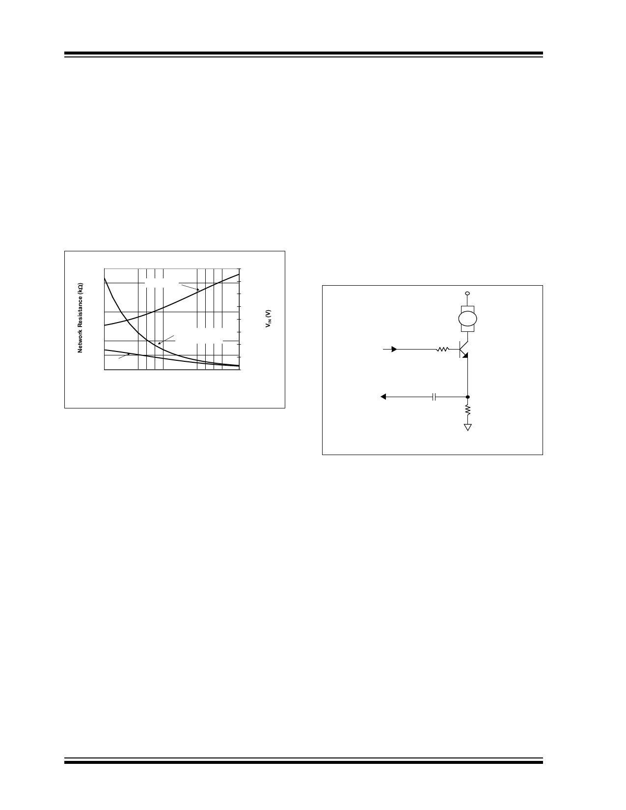
reasonable values for RSENSE. Figure 5-3 illustrates a
typical SENSE network.
VOUT
FAN
RISO
715
SENSE
CSENSE
(0.1 µF typical)
RSENSE
Note: See Table 5-1 for RSENSE values.
FIGURE 5-3:
Typical Sense Network.
The required value of RSENSE will change with the cur-
rent rating of the fan and the fan current waveshape. A
key point is that the current rating of the fan specified
by the manufacturer may be a worst-case rating, with
the actual current drawn by the fan being lower. For the
purposes of setting the value for RSENSE, the operating
fan current should be measured to get the nominal
value. This can be done by using an oscilloscope cur-
rent probe or by using a voltage probe with a low value
resistor (0.5). Another good tool for this exercise is
the TC642 Evaluation Board. This board allows the
RSENSE and CSENSE values to be easily changed while
allowing the voltage waveforms to be monitored to
ensure the proper levels are being reached.
Table 5-1 shows values of RSENSE according to the
nominal operating current of the fan. The fan currents
are average values. If the fan current falls between two
of the values listed, use the higher resistor value.
DS21756C-page 18
2002-2013 Microchip Technology Inc.
Share Link: 