DSP56852PB View Datasheet(PDF) - Motorola => Freescale
Part Name
Description
Manufacturer
DSP56852PB Datasheet PDF : 44 Pages
| |||
Freescale Semiconductor, Inc.
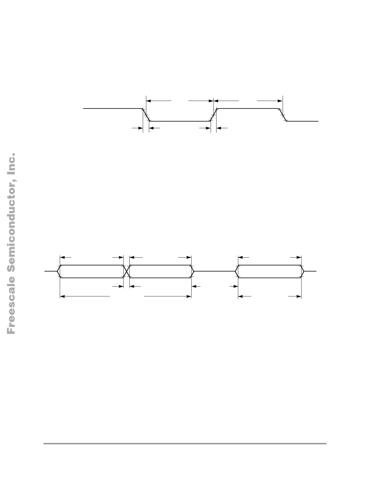
4.4 AC Electrical Characteristics
Timing waveforms in Section 4.2 are tested with a VIL maximum of 0.8V and a VIH minimum of 2.0V for
all pins except XTAL, which is tested using the input levels in Section 4.2. In Figure 6 the levels of VIH
and VIL for an input signal are shown.
VIH
Low
Input Signal
Midpoint1
Fall Time
VIL
High
Rise Time
90%
50%
10%
Note: The midpoint is VIL + (VIH – VIL)/2.
Figure 6. Input Signal Measurement References
Figure 7 shows the definitions of the following signal states:
• Active state, when a bus or signal is driven, and enters a low impedance state
• Tri-stated, when a bus or signal is placed in a high impedance state
• Data Valid state, when a signal level has reached VOL or VOH
• Data Invalid state, when a signal level is in transition between VOL and VOH
Data1 Valid
Data1
Data2 Valid
Data2
Data Invalid State
Data Active
Data
Tri-stated
Data3 Valid
Data3
Data Active
Figure 7. Signal States
4.5 External Clock Operation
The DSP56852 system clock can be derived from a crystal or an external system clock signal. To generate
a reference frequency using the internal oscillator, a reference crystal must be connected between the
EXTAL and XTAL pins.
4.5.1 Crystal Oscillator for use with PLL
The internal oscillator is designed to interface with a parallel-resonant crystal resonator in the frequency
range specified for the external crystal in Table 9. In Figure 8 a typical crystal oscillator circuit is shown.
Follow the crystal supplier’s recommendations when selecting a crystal, because crystal parameters
determine the component values required to provide maximum stability and reliable start-up. The crystal
and associated components should be mounted as close as possible to the EXTAL and XTAL pins to
minimize output distortion and start-up stabilization time.
18
DSP56852 Technical Data
For More Information On This Product,
Preliminary
Go to: www.freescale.com
Share Link: 