LA70100M View Datasheet(PDF) - SANYO -> Panasonic
Part Name
Description
Manufacturer
LA70100M Datasheet PDF : 16 Pages
| |||
Functional Description
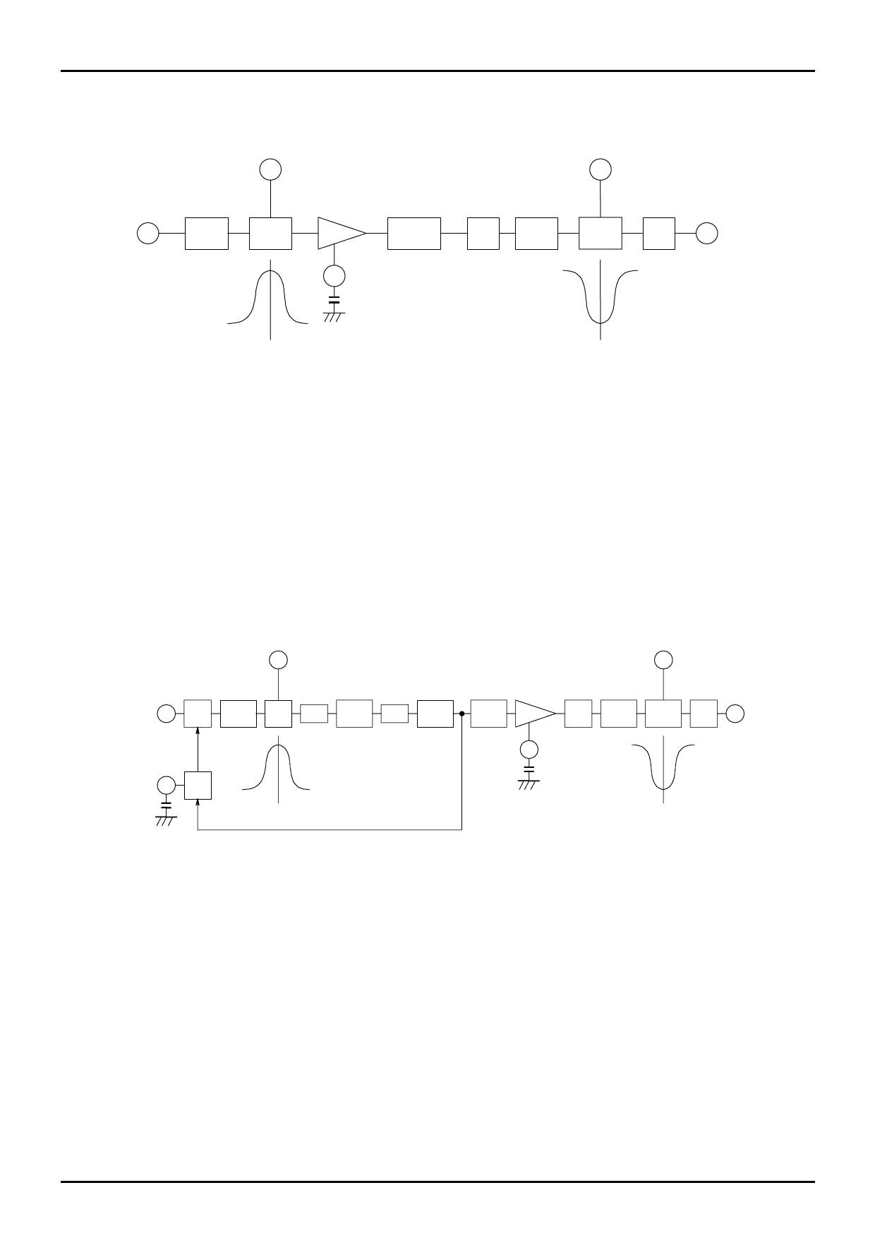
(1) REC mode
MONITOR
OUTPUT
20
LA70100M
MONITOR
OUTPUT
11
4.3MHz 4.3MHz
16
BPF
BELL
LIM
VIDEO SIGNAL
INPUT
19
1/4
DIVIDER
SYNC 1.1MHz
GATE BPF
1.1MHz
A-BELL
REC
MUTE
12
LOW CHROMA
SIGNAL OUTPUT
4.286MHz
1.107MHz
Fig.1 Signal flow in REC mode
Video signals which have been input to Pin 16, pass through the 4.3MHz BPF with unnecessary component (ex. sync signal)
removed, and the component of chroma signal is extracted. And the characteristics during transmission are made flat through a
4.3MHz-BELL filter. The center frequency of this filter has automatically been adjusted to be 4.286MHz. After that, the
limiter amplifier limits the amplitude, and the chroma signal frequency is converted to 1/4 by a divide-by-four circuit. Though
the limiter amplifier amplifies the noise of non-signal parts of the converted signal during synchronization, the sync gate circuit
cleans the peripherals of the sync signal. Still more, since this signal has rectangle waveforms, it contains unnecessary
component of frequency. To remove it, the signal passes through a 1.1MHz BPF and then is input to 1.1MHz-A-BELL filter.
The center frequency of this filter is automatically adjusted to 1.0715MHz, and has opposite characteristics to BELL
characteristics. Afterwards, unnecessary components around the sync signal are muted, low-band chroma signal is output to
Pin 12 through a buffer.
(2) PB mode
MONITOR
OUTPUT
11
MONITOR
OUTPUT
20
14
AGC 1.1MHz PB
AMP BPF BELL
X2
2.2MHz
BPF
X2
2.2MHz
TRAP
4.3MHz
BPF
LIM
LOW CHROMA
SIGNAL INPUT
VM
19
15
AGC
DET
1.107MHz
SYNC
GATE
4.3MHz
BPF
4.3MHz
A-BELL
PB
MUTE
18
PB CHROMA
SIGNAL OUTPUT
4.286MHz
Fig.2 Signal flow in PB mode
The low chroma signal that has been input from Pin 14 enters AGC amplifier and is controlled so that the output level of 4
times multiplier be constant. Then it passes through the 1.1MHz BPF with unnecessary components removed before input to
1.1MHz-BELL filter. The center frequency of this filter has automatically been adjusted to be 1.0715MHz. Next, this signal
passes through the 4 times multiplier composed of a 2× multiplier + 2.2 MHz BPF + 2× multiplier + 2.2MHz TRAP + 4.3MHz
BPF with unnecessary component of frequency generated in multiplier removed. The first 2× multiplier has auto carrier leak
balancer allowing beat obstruction reduced. Next, this signal is limited pulse amplitude by limiting amplifier, then noises
around the sync signal owing to limited amplifier are cleaned by the sync gate circuit. This signal has a rectangle waveform
and contains unnecessary components of frequency. To remove it, the signal passes through a 4.3MHz BPF before input to
4.3MHz-BELL filter. The center frequency of this filter is automatically adjusted to 4.286MHz, allowing the BELL
characteristics to the state during transmission. Afterwards, unnecessary components around the sync signal are muted,
low-band chroma signal is output to Pin 18 through a buffer.
No.7204-7/16
Share Link: 