LH28F008SCL-12 View Datasheet(PDF) - Sharp Electronics
Part Name
Description
Manufacturer
LH28F008SCL-12 Datasheet PDF : 49 Pages
| |||
LHF08CH3
15
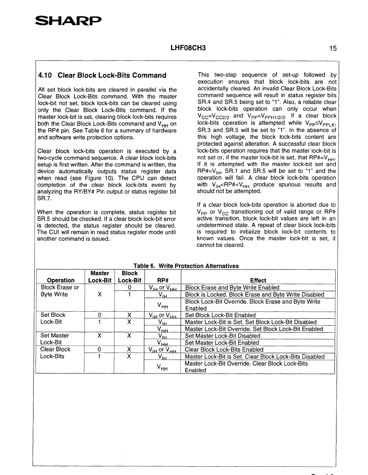
4.10 Clear Block Lock-Bits Command
i All set block lock-bits are cleared in parallel via the
Clear Block Lock-Bits command. With the master
lock-bit not set, block lock-bits can be cleared using
only the Clear Block Lock-Bits command. If the
master lock-bit is set, clearing block lock-bits requires
both the Clear Block Lock-Bits command and V,, on
the RP# pin. See Table 6 for a summary of hardware
and software write protection options.
Clear block lock-bits operation is executed by a
two-cycle command sequence. A clear block lock-bits
setup is first written. After the command is written, the
device automatically outputs status register data
when read (see Figure 10). The CPU can detect
completion of the clear block lock-bits event by
analyzing the RY/BY# Pin output or status register bit
SR.7.
When the operation is complete, status register bit
SR.5 should be checked. If a clear block lock-bit error
is detected, the status register should be cleared.
The CUI will remain in read status register mode until
another command is issued.
1
This two-step sequence of set-up followed by
execution ensures that block lock-bits are not
accidentally cleared. An invalid Clear Block Lock-Bits
command sequence will result in status register bits
SR.4 and SR.5 being set to вҖң1 IвҖҷ. Also, a reliable clear
block lock-bits operation can only occur when
Vcc=Vcc2,s and VPP=VPPH1,2,3. If a clear block
lock-bits operation is attempted while V,,rV,,,,,
SR.3 and SR.5 will be set to вҖң1вҖқ. In the absence of
this high voltage, the block lock-bits content are
protected against alteration. A successful clear block
lock-bits operation requires that the master lock-bit is
not set or, if the master lock-bit is set, that RP#=V,,.
If it is attempted with the master lock-bit set and
RP#=V,,, SR.l and SR.5 will be set to вҖң1вҖқ and the
operation will fail. A clear block lock-bits operation
with V,,cRP#cV,,
p reduce spurious results and
should not be attempted.
If a clear block lock-bits operation is aborted due to
V,, or Vcc transitioning out of valid range or RP#
active transition, block lock-bit values are left in an
undetermined state. A repeat of clear block lock-bits
is required to initialize block lock-bit contents to
known values. Once the master lock-bit is set, it
cannot be cleared.
Operation
Block Erase or
Byte Write
Master
Lock-Bit
X
Set Block
Lock-Bit
-
Set Master
Lock-Bit
-
Clear Block
Lock-Bits
Table 6. Write Protection Alternatives
Block
Lock-Bit
RP#
Effect
0
V,, or VHH Block Erase and Byte Write Enabled
1
V,,
Block is Locked. Block Erase and Byte Write Disabled
\I
Block Lock-Bit Override. Block Erase and Bvte Write
вҖҳHH
Enabled
X
VIH or VHH Set Block Lock-Bit Enabled
X
V,,
Master Lock-Bit is Set. Set Block Lock-Bit Disabled
VHH
Master Lock-Bit Override. Set Block Lock-Bit Enabled
X
V,,
Set Master Lock-Bit Disabled
Vr+
Set Master Lock-Bit Enabled
X
V,, , or V,, Clear Block Lock-Bits Enabled
X
V,H
Master Lock-Bit is Set. Clear Block Lock-Bits Disabled
.r,v-r-a1s-r-el r
--I~m.rh
LOCK-~
uver-n..a.-eI-.
hLrl-e-ar
вҖң,--,L# --I _.I
DIOCK LOCK-ms
вҖҳHH
Enabled
/
Rev. 1.0
Share Link: 