TC7136 View Datasheet(PDF) - Microchip Technology
Part Name
Description
Manufacturer
TC7136 Datasheet PDF : 22 Pages
| |||
5.0 DIGITAL SECTION
The TC7136/A contains all the segment drivers neces-
sary to directly drive a 3-1/2 digit LCD. An LCD back-
plane driver is included. The backplane frequency is
the external clock frequency divided by 800. For three
conversions per second, the backplane frequency is
60Hz with a 5V nominal amplitude. When a segment
driver is in phase with the backplane signal, the seg-
ment is OFF. An out-of-phase segment drive signal
causes the segment to be ON, or visible. This AC drive
configuration results in negligible DC voltage across
each LCD segment, ensuring long LCD life. The polar-
ity segment driver is ON for negative analog inputs. If
VIN+ and VIN- are reversed, this indicator would
reverse.
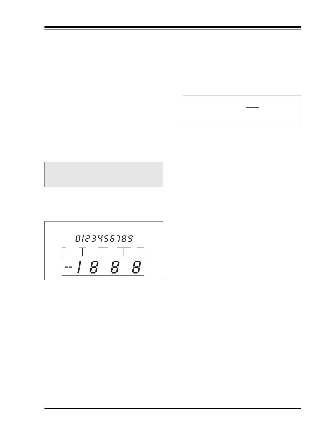
On the TC7136/A, when the TEST pin is pulled to V+,
all segments are turned ON. The display reads -1888.
During this mode, the LCD segments have a constant
DC voltage impressed.
Note:
Do not leave the display in this mode for
more than several minutes. LCDs may be
destroyed if operated with DC levels for
extended periods.
The display font and segment drive assignment are
shown in Figure 5-1.
FIGURE 5-1:
DISPLAY FONT AND
SEGMENT ASSIGNMENT
Display Font
1000's 100's
10's
1's
5.1 System Timing
The oscillator frequency is divided by 4 prior to clocking
the internal decade counters. The four-phase mea-
surement cycle takes a total of 4000 counts, or 16,000
clock pulses. The 4000 count cycle is independent of
input signal magnitude.
© 2005 Microchip Technology Inc.
TC7136/TC7136A
Each phase of the measurement cycle has the
following length:
1. Auto-zero phase: 3000 to 2900 counts
(1200 to 11,600 clock pulses)
2. Signal integrate: 1000 counts
(4000 clock pulses)
This time period is fixed. The integration period is:
EQUATION 5-1:
Where:
tSI
=
4000
⎛
⎝
1
FOSC
⎞
⎠
FOSC is the externally set clock frequency.
3. Reference integrate: 0 to 2000 counts
4. Zero integrator: 11 to 640 counts
The TC7136 is a drop-in replacement for the TC7126
and ICL7126. The TC7136A offers a greatly improved
internal reference temperature coefficient. Minor com-
ponent value changes are required to upgrade existing
designs and improve the noise performance.
6.0 COMPONENT VALUE
SELECTION
6.1 Auto-Zero Capacitor (CAZ)
The CAZ capacitor size has some influence on system
noise. A 0.47μF capacitor is recommended for 200mV
full scale applications, where 1LSB is 100μV. A 0.1μF
capacitor is adequate for 2V full scale applications. A
Mylar type dielectric capacitor is adequate.
6.2 Reference Voltage Capacitor
(CREF)
The reference voltage, used to ramp the integrator out-
put voltage back to zero during the reference integrate
phase, is stored on CREF. A 0.1μF capacitor is accept-
able when VREF- is tied to analog common. If a large
Common mode voltage exists (VREF- ≠ analog com-
mon) and the application requires a 200mV full scale,
increase CREF to 1μF. Rollover error will be held to less
than 0.5 count. A Mylar type dielectric capacitor is
adequate.
6.3 Integrating Capacitor (CINT)
CINT should be selected to maximize integrator output
voltage swing without causing output saturation. Ana-
log common will normally supply the differential voltage
reference in this case, a ±2V full scale integrator output
swing is satisfactory. For 3 readings per second
(FOSC = 48kHz), a 0.047μF value is suggested. For
one reading per second, 0.15μF is recommended. If a
different oscillator frequency is used, CINT must be
changed in inverse proportion to maintain the nominal
±2V integrator swing.
DS21461C-page 11
Share Link: 