LS7166 View Datasheet(PDF) - LSI Corporation
Part Name
Description
Manufacturer
LS7166 Datasheet PDF : 15 Pages
| |||
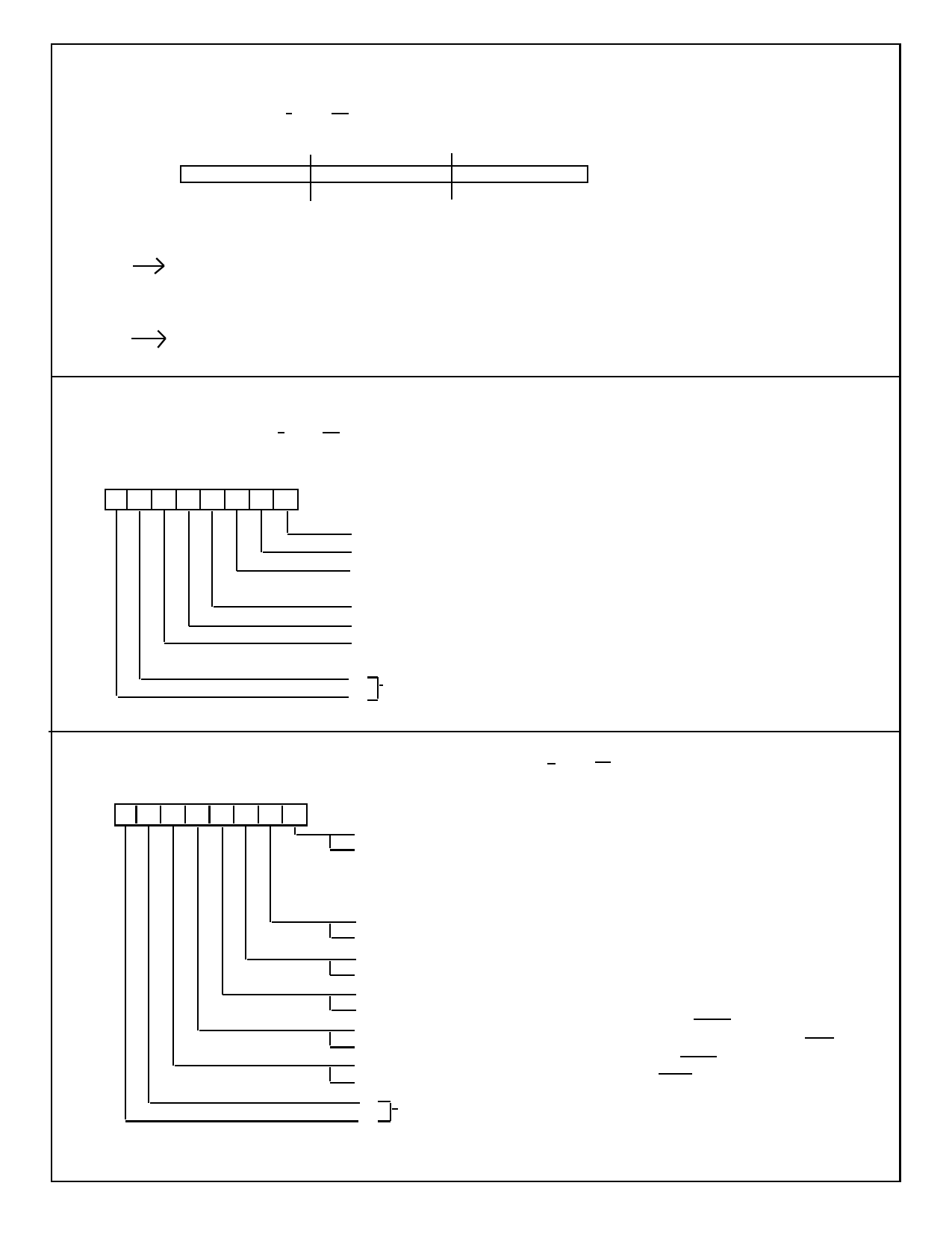
PR (Preset register). The PR is the input port for the CNTR. The CNTR is loaded with a 24 bit data via the PR. The
data is first written into the PR in 3 WRITE cycle sequence of Byte 0 (PR0), Byte 1 (PR1) and Byte 2 (PR2).
The address pointer for PR0/PR1/PR2 is automatically incremented with each write cycle.
Accessed by: WRITE when C/D = 0, CS = 0.
Bit #
7----------0 7---------- 0 7----------0
PR2
(BYTE 2)
PR1
(BYTE 1)
PR0
(BYTE 0)
Standard Sequence for Loading PR and Reading CNTR:
1
MCR
; Reset PR address pointer
WRITE PR
; Load Byte 0 and into PR0 increment address
WRITE PR
; Load Byte 1 and into PR1 increment address
WRITE PR
; Load Byte 2 and into PR3 increment address
8
MCR ; Transfer PR to CNTR
MCR (Master Control Register). Performs register reset and load operations. Writing a "non-zero” word to MCR does
not require a follow-up write of an “all-zero” word to terminate a designated operation.
Accessed by: WRITE when C/D = 1, CS = 0.
Bit # 7 6 5 4 3 2 1 0
00
1: Reset PR/OL address pointer
1: Transfer CNTR to OL (24 bits)
1: Reset CNTR, BWT and CYT. Set SIGN bit.
(CNTR = 0, BWT = 0, CYT = 0, SIGN = 1)
1: Transfer PR to CNTR (24 bits)
1: Reset COMPT (COMPT = 0)
1: Master reset. Reset CNTR, ICR, OCCR, QR, BWT, CYT, OL
COMPT, and PR/OL address pointer. Set PR (PR = FFFFFF) and SIGN.
0: Select MCR
0:
NOTE: Control functions may be combined.
ICR (Input Control Register). Initializes counter input operating modes.
Accessed by: WRITE when C/D = 1, CS = 0.
Bit # 7 6 5 4 3 2 1 0
01
0: Input A = Up count input, Input B = Down count input
1: Input A = Count input, Input B = Count direction input (overridden in
quadrature mode) where B = 0 selects up count mode and B = 1
selects Down count mode.
(NOTE: During counting operation B may switch only when A = 1.)
0: NOP
1: Increment CNTR once (A/B = 1, if enabled)
0: NOP
1: Decrement CNTR once (A/B = 1, if enabled)
0: Disable inputs A/B
1: Enable inputs A/B
0: Initialize Pin 4 as CNTR Reset input (Pin 4 = RCTR)
1: Initialize Pin 4 as Enable/Disable gate for A/B inputs (Pin 4 = ABGT)
0: Initialize Pin 3 as CNTR load input (Pin 3 = LCTR)
1: Initialize Pin 3 as OL load input (Pin 3 = LLTC)
1: Select ICR
0:
NOTE: Control functions may be combined.
7166-110103-2
Share Link: 