DS17285(1998) View Datasheet(PDF) - Dallas Semiconductor -> Maxim Integrated
Part Name
Description
Manufacturer
DS17285 Datasheet PDF : 32 Pages
| |||
DS17285/DS17287
tion, the kickstart feature can allow the system to be
powered up in response to a low going transition on the
KS pin, without operating voltage applied to the VCC pin.
As a result, system power may be applied upon such
events as a key closure, or modem ring detect signal. In
order to use either the wake up or the kickstart features,
the DS17285/DS17287 must have an auxiliary battery
connected to the VBAUX pin and the oscillator must be
running and the countdown chain must not be in reset
(Register A DV2, DV1, DV0 = 01X). If DV2, DV1, and
DV0 are not in this required state, the PWR pin will not
be driven low in response to a kickstart or wakeup condi-
tion, while in battery–backed mode.
The wake up feature is controlled through the Wake up
Interrupt Enable bit in extended control register 4B
(WIE, bank 1, 04BH). Setting WIE to 1 enables the
wake up feature, clearing WIE to 0 disables it. Similarly,
the kickstart feature is controlled through the Kickstart
Interrupt Enable bit in extended control register 4B
(KSE, bank 1, 04BH).
A wake up sequence will occur as follows: When wake
up is enabled via WIE = 1 while the system is powered
down (no VCC voltage), the clock/calendar will monitor
the current date for a match condition with the date
alarm register (bank 1, register 049H). In conjunction
with the date alarm register, the hours, minutes, and
seconds alarm bytes in the clock/calendar register map
(bank 0, registers 05H, 03H, and 01H) are also moni-
tored. As a result, a wake up will occur at the date and
time specified by the date, hours, minutes, and seconds
alarm register values. This additional alarm will occur
regardless of the programming of the AIE bit (bank 0,
register B, 0BH). When the match condition occurs, the
PWR pin will automatically be driven low. This output
can be used to turn on the main system power supply
which provides VCC voltage to the DS17285/DS17287
as well as the other major components in the system.
Also at this time, the Wake Up flag (WF, bank 1, register
04AH) will be set, indicating that a wake up condition
has occurred.
A kickstart sequence will occur when kickstarting is
enabled via KSE = 1. While the system is powered
down, the KS input pin will be monitored for a low going
transition of minimum pulse width tKSPW. When such a
transition is detected, the PWR line will be pulled low, as
it is for a wake up condition. Also at this time, the Kick-
start Flag (KF, bank 1, register 04AH) will be set, indicat-
ing that a kickstart condition has occurred.
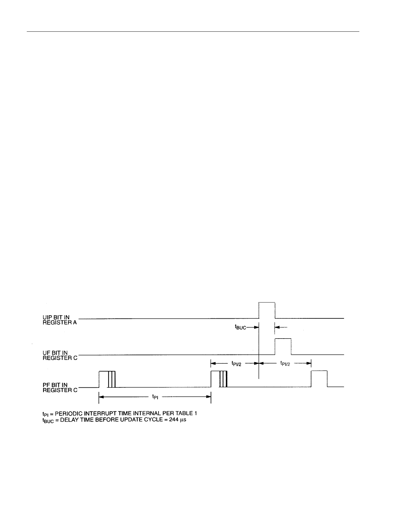
The timing associated with both the wake up and kick-
starting sequences is illustrated in the Wake Up / Kick-
start Timing Diagram in the Electrical Specifications
section of this data sheet. The timing associated with
these functions is divided into 5 intervals, labeled 1–5 on
the diagram.
The occurrence of either a kickstart or wake up condi-
tion will cause the PWR pin to be driven low, as
described above. During interval 1, if the supply voltage
on the DS17285/DS17287 VCC pin rises above the 3
volt power fail level before the power on timeout period
(tPOTO) expires, then PWR will remain at the active low
level. If VCC does not rise above the 3 volt power fail
voltage in this time, then the PWR output pin will be
turned off and will return to its high impedance level. In
this event, the IRQ pin will also remain tri–stated. The
interrupt flag bit (either WF or KF) associated with the
attempted power on sequence will remain set until
cleared by software during a subsequent system
power on.
If VCC is applied within the timeout period, then the sys-
tem power on sequence will continue as shown in inter-
vals 2–5 in the timing diagram. During interval 2, PWR
will remain active and IRQ will be driven to its active low
level, indicating that either WF or KF was set in initiating
the power on. In the diagram KS is assumed to be pulled
up to the VBAUX supply. Also at this time, the PAB bit will
be automatically cleared to 0 in response to a success-
ful power on. The PWR line will remain active as long as
the PAB remains cleared to 0.
At the beginning of interval 3, the system processor has
begun code execution and clears the interrupt condition
of WF and/or KF by writing zeroes to both of these con-
trol bits. As long as no other interrupt within the
DS17285/DS17287 is pending, the IRQ line will be
taken inactive once these bits are reset. Execution of
the application software may proceed. During this time,
both the wake up and kickstart functions may be used to
generate status and interrupts. WF will be set in
response to a date, hours, minutes, and seconds match
condition. KF will be set in response to a low going tran-
sition on KS. If the associated interrupt enable bit is set
(WIE and/or KSE) then the IRQ line will driven active low
in response to enabled event. In addition, the other pos-
sible interrupt sources within the DS17285/DS17287
may cause IRQ to be driven low. While system power is
applied, the on chip logic will always attempt to drive the
PWR pin active in response to the enabled kickstart or
wake up condition. This is true even if PWR was pre-
030598 15/32
Share Link: 