DSP56321 View Datasheet(PDF) - Freescale Semiconductor
Part Name
Description
Manufacturer
DSP56321 Datasheet PDF : 84 Pages
| |||
AC Electrical Characteristics
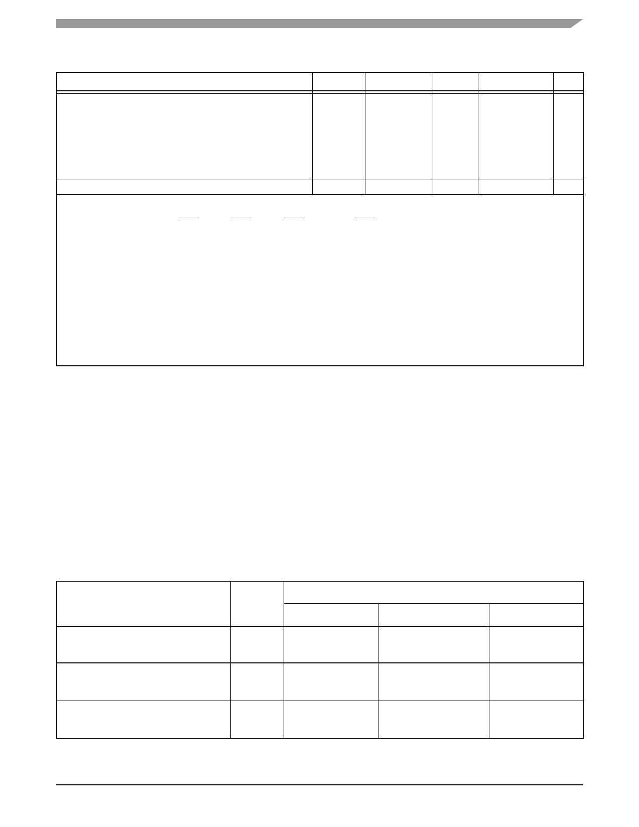
Table 2-3. DC Electrical Characteristics7
Characteristics
Symbol
Min
Typ
Max
Unit
Internal supply current:
• In Normal mode3
— at 200 MHz
ICCI
—
190
—
mA
— at 220 MHz
— at 240 MHz
—
200
—
210
—
mA
—
mA
— at 275 MHz
• In Wait mode4
• In Stop mode5
Input capacitance6
ICCW
ICCS
CIN
—
235
—
25
—
15
—
—
—
mA
—
mA
—
mA
10
pF
Notes: 1. Power-up sequence: During power-up, and throughout the DSP56321 operation, VCCQH voltage must always be higher or
equal to VCCQL voltage.
2. Refers to MODA/IRQA, MODB/IRQB, MODC/IRQC, and MODD/IRQD pins.
3. Section 4.3 provides a formula to compute the estimated current requirements in Normal mode. To obtain these results, all
inputs must be terminated (that is, not allowed to float). Measurements are based on synthetic intensive DSP benchmarks (see
Appendix A). The power consumption numbers in this specification are 90 percent of the measured results of this benchmark.
This reflects typical DSP applications.
4. To obtain these results, all inputs must be terminated (that is, not allowed to float).
5. To obtain these results, all inputs not disconnected at Stop mode must be terminated (that is, not allowed to float), and the
DPLL and on-chip crystal oscillator must be disabled.
6. Periodically sampled and not 100 percent tested.
7. VCCQH = 3.3 V ± 0.3 V, VCQLC = 1.6 V ± 0.1 V; TJ = –40°C to +100 °C, CL = 50 pF
8. This characteristic does not apply to XTAL.
9. Driving EXTAL to the low VIHX or the high VILX value may cause additional power consumption (DC current). To minimize
power consumption, the minimum VIHX should be no lower than
0.9 × VCCQH and the maximum VILX should be no higher than 0.1 × VCCQH.
2.4 AC Electrical Characteristics
The timing waveforms shown in the AC electrical characteristics section are tested with a VIL maximum of 0.3 V
and a VIH minimum of 2.4 V for all pins except EXTAL, which is tested using the input levels shown in Notes 7
and 9 of the previous table. AC timing specifications, which are referenced to a device input signal, are measured in
production with respect to the 50 percent point of the respective input signal’s transition. DSP56321 output levels
are measured with the production test machine VOL and VOH reference levels set at 0.4 V and 2.4 V, respectively.
Note: Although the minimum value for the frequency of EXTAL is 0 MHz, the device AC test conditions are 16
MHz and rated speed with the DPLL enabled.
2.4.1 Internal Clocks
Table 2-4. Internal Clocks
Characteristics
Internal operating frequency
• With DPLL disabled
• With DPLL enabled
Internal clock cycle time
• With DPLL disabled
• With DPLL enabled
Internal clock high period
• With DPLL disabled
• With DPLL enabled
Symbol
f
TC
TH
Min
—
—
—
—
—
0.49 × TC
Expression
Typ
Ef/2
(Ef × MF)/(PDF × DF)
2 × ETC
ETC × PDF × DF/MF
ETC
—
Max
—
—
—
—
—
0.51 × TC
DSP56321 Technical Data, Rev. 11
Freescale Semiconductor
2-3
Share Link: 