CDP1805AC View Datasheet(PDF) - Intersil
Part Name
Description
Manufacturer
CDP1805AC Datasheet PDF : 30 Pages
| |||
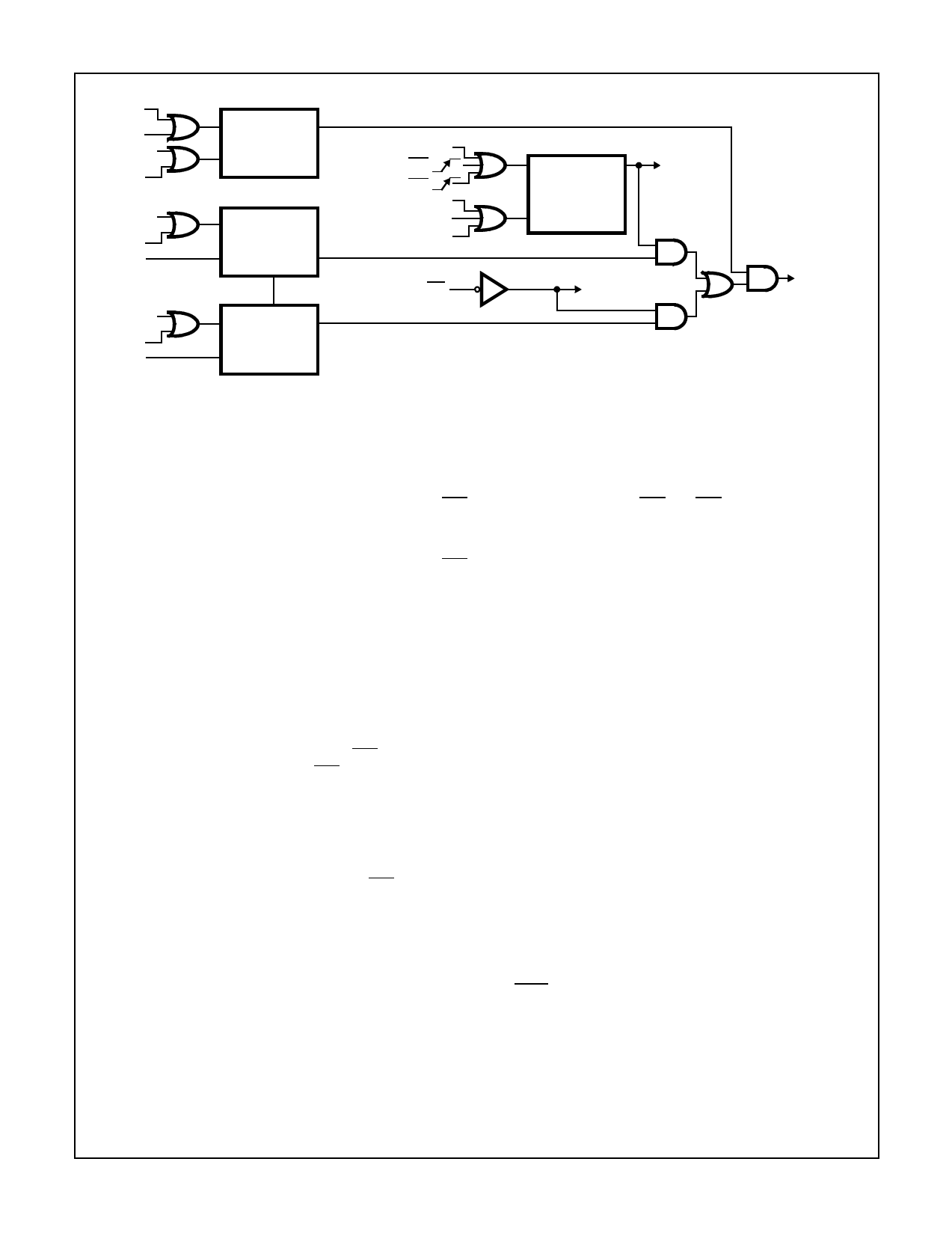
CDP1805AC, CDP1806AC
RET
RESET
S3
DIS
CIE
RESET
CID
XIE
RESET
XID
S
MASTER
INTERRUPT
Q
ENABLE
R
FF
(MIE)
S
COUNTER
INTERRUPT
ENABLE
R
FF
(CIE)
Q
COUNTER
UNDERFLOW
PULSE MODE EF1
PULSE MODE EF2
BCI
RESET
LDC • COUNTER
STOPPED
EXTERNAL INT
S
EXTERNAL
INTERRUPT
Q
ENABLE
R
FF
(XIE)
MIE
S
Q
COUNTER
INTERRUPT
LATCH
(CIL)
R
TO BRANCH
LOGIC (BCI)
CI
XI
TO BRANCH
LOGIC (BXI)
FIGURE 6. INTERRUPT LOGIC CONTROL DIAGRAM
INTERRUPT
REQUESTS
The Counter/Timer has the following five programmable
modes:
1. Event Counter 1: Input to counter is connected to the EF1
terminal. The high-to-low transition decrements the
counter.
2. Event Counter 2: Input to counter is connected to the EF2
terminal. The high-to-low transition decrements the
counter.
3. Timer: Input to counter is from the divide by 32 prescaler
clocked by TPA. The prescaler is decremented on the
low-to-high transition of TPA. The divide by 32 prescaler
is reset when the counter is in a mode other than the
Timer mode, system RESET, or stopped by a STPC.
4. Pulse Duration Measurement 1: Input to counter con-
nected to TPA. Each low-to-high transition of TPA decre-
ments the counter if the input signal at EF1 terminal (gate
input) is low. On the transition of EF1 to the positive state,
the count is stopped, the mode is cleared, and the inter-
rupt request latched. If the counter underflows while the
input is low, interrupt will also be set, but counting will
continue.
5. Pulse Duration Measurement 2: Operation is identical to
Pulse Duration Measurement 1, except EF2 is used as
the gate input.
The modes can be changed without affecting the stored
count.
Those modes which use EF1 and EF2 terminals as inputs do
not exclude testing these flags for branch instructions.
The Stop Counter (STPC) instruction clears the counter
mode and stops counting. The STPC instruction should be
executed prior to a GEC instruction, if the counter is in the
Event Counter Mode 1 or 2.
In addition to the five programmable modes, the Decrement
Counter instruction (DTC) enables the user to count in soft-
ware. In order to avoid conflict with counting done in the
other modes, the instruction should be used only after the
mode has been cleared by a Stop Counter instruction.
The Enable Toggle Q instruction (ETQ) connects the Q-line
flip-flop to the output of the counter, such that each time the
counter decrements from 01 to its next value, the Q output
changes state. This action is independent of the counter
mode and the Interrupt Enable flip-flops. The Enable Toggle
Q condition is cleared by an LDC with the Counter/Timer
stopped, system Reset, or a BCl with Cl = 1.
NOTE: SEQ and REQ instructions are independent of ETQ, they
can SET or RESET Q while the Counter is running.
On-Board Clock (See Figure 8, Figure 9 and Figure 10)
Clock circuits may use either an external crystal or an RC
network.
A typical crystal oscillator circuit is shown in Figure 8. The
crystal is connected between terminals 1 and 39 (CLOCK
and XTAL) in parallel with a resistance, RF (1mΩ typ). Fre-
quency trimming capacitors, CIN and COUT, may be required
at terminals 1 and 39. For additional information on crystal
oscillators, see lCAN-6565.
13
Share Link: 