CDP1805AC View Datasheet(PDF) - Intersil
Part Name
Description
Manufacturer
CDP1805AC Datasheet PDF : 30 Pages
| |||
CDP1805AC, CDP1806AC
The function of the modes are defined as follows:
Reset
The levels on the CDP1805A and CDP1806A external signal
lines will asynchronously be forced by RESET to the follow-
ing states:
Q=0
MRD = 1
TPB = 0
SC1, SC0 = 0,1 BUS 0-7 = 0
(EXECUTE)
MA0-7 = RO.1
N0, N1, N2 = 0, 0, 0 TPA = 0
MWR = 1
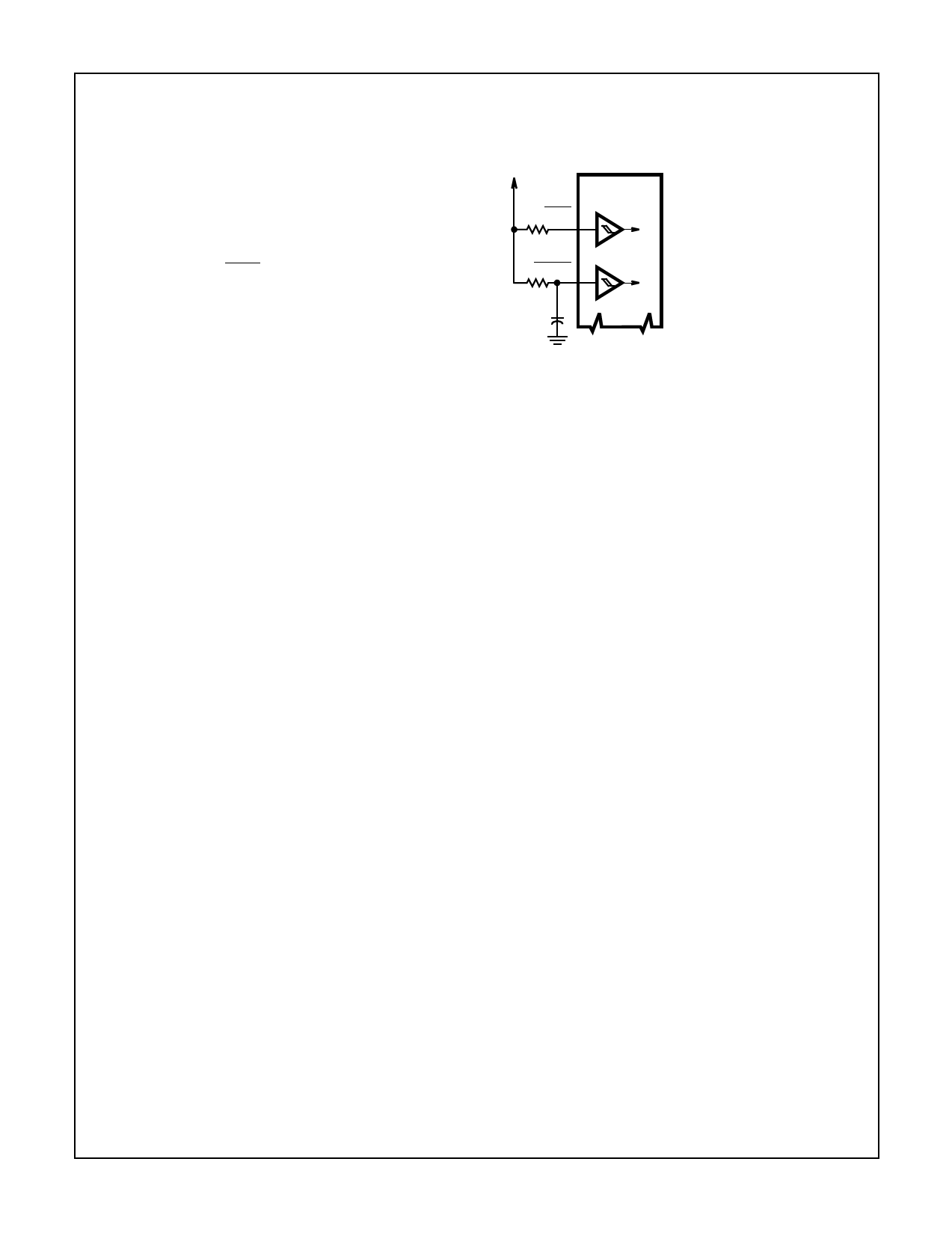
Power-up Reset/Run Circuit
Power-up Reset/Run can be realized with the circuit shown
in Figure 11.
VDD
RP WAIT
CDP1805AC
CDP1806AC
THE RC TIME CONSTANT
SHOULD BE GREATER THAN
THE OSCILLATOR START-UP
TIME (TYPICALLY 20ms)
RX CLEAR
Internal Changes Caused By RESET are:
l, N Instruction Register is cleared to 00. XlE and CIE are set
to allow interrupts following initialize. ClL is cleared (any
pending counter interrupt is cleared), counter is stopped, the
counter mode is cleared, and ETQ is disabled.
CX
FIGURE 11. RESET/RUN DIAGRAM
Initialization Cycle
The first machine cycle following termination of RESET is an
initialization cycle which requires 9 clock pulses. During this
cycle the CPU remains in S1 and the following additional
changes occur:
1 → MlE
X, P → T (The old value of X, P will be put into T. This
only has meaning following an orderly Reset with power
applied).
X, P, RO ← 0 (X, P, and RO are cleared).
Interrupt and DMA servicing is suppressed during the initial-
ization cycle. The next cycle is an S0 or an S2 but never an
S1 or S3.The use of a 71 instruction followed by 00 at mem-
ory locations 0000 and 0001, may be used to reset MIE so
as to preclude interrupts until ready for them.
Reset and Initialize Do Not Affect:
D (Accumulator)
DF
R1, R2, R3, R4, R5, R6, R7, R8, R9, FA, RB, RC, RD, RE, RF
CH (Counter Holding Register)
Counter (the counter is stopped but the value is unaffected)
Pause
Pause is a low power mode which stops the internal CPU
timing generator and freezes the state of the processor. The
CPU may be held in the Pause mode indefinitely. Hardware
pause can occur at two points in a machine cycle, on the
low-to-high transition of either TPA or TPB. A TPB pause can
also be initiated by software with the execution of an IDLE
instruction. In the pause mode, the oscillator continues to run
but subsequent clock transitions are ignored. TPA and TPB
remain at their previous state (see Figure 12).
Pause is entered from RUN by dropping WAIT low. Appropri-
ate Setup and Hold times must be met.
If Pause is entered while in the event counter mode, the
appropriate Flag transition will continue to decrement the
counter.
Hardware-initiated pause is exited to RUN by raising the
Wait line high. Pause entered with an IDLE instruction
requires DMA, INTERRUPT or RESET to resume execution.
Run
May be initiated from the Pause or Reset mode functions. If
initiated from Pause, the CPU resumes operation at the
point it left off. If paused at TPA, it will resume on the next
high-to-low clock transition, while if paused at TPB, it will
resume on the next low-to-high clock transition (see Figure
12). When initiated from the Reset operation, the first
machine cycle following Reset is always the initialization
cycle. The initialization cycle is then followed by a DMA (S2)
cycle or fetch (S0) from location 0000 in memory.
Schmitt Trigger Inputs
All inputs except BUS 0-BUS 7 and ME contain a Schmitt
Trigger circuit, which is especially useful on the CLEAR input
as a power-up RESET (see Figure 11) and the CLOCK input
(see Figure 8 and Figure 9).
15
Share Link: 