LH28F008SC View Datasheet(PDF) - Sharp Electronics
Part Name
Description
Manufacturer
LH28F008SC Datasheet PDF : 38 Pages
| |||
LH28F008SC
8M (1M × 8) Flash Memory
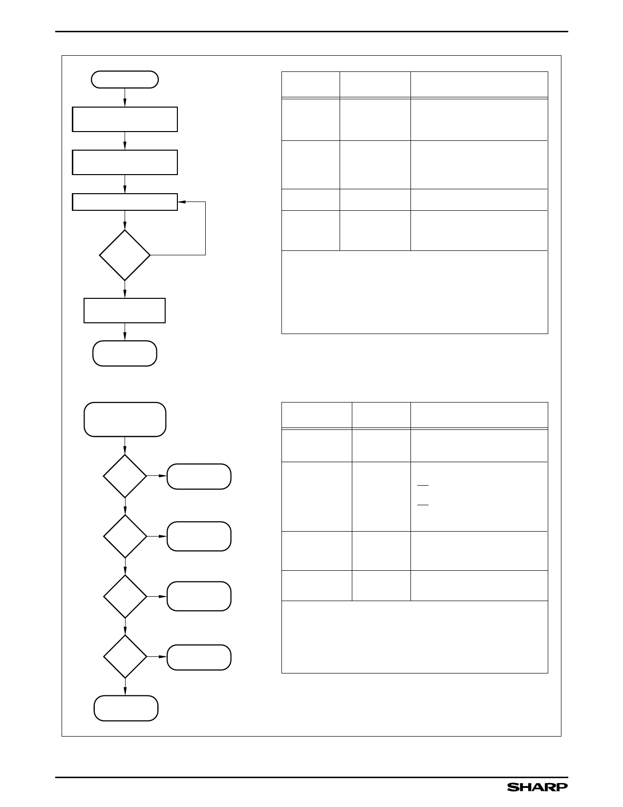
START
WRITE 60H
BLOCK/DEVICE ADDRESS
WRITE 01H/F1H
BLOCK/DEVICE ADDRESS
READ STATUS REGISTER
SR.7 = 0
1
FULL STATUS
CHECK IF DESIRED
BUS
OPERATION
COMMAND
COMMENTS
Write
Write
Read
Set
Block/Master
Lock-Bit Setup
Data = 60H
Addr = Block Address (Block),
Device Address (Master)
Set
Block or Master
Lock-Bit Confirm
Data = 01H (Block)
F1H (Master)
Addr = Block Address (Block),
Device Address (Master)
Status Register Data
Standby
Check SR.7
1 = WSM Ready
0 = WSM Busy
Repeat for subsequent lock-bit set operations.
Full status check can be done after each lock-bit set operation
or after a sequence of lock-bit set operations.
Write FFH after the last lock-bit set operation to place device
in read array mode.
SET LOCK-BIT
COMPLETED
FULL STATUS CHECK PROCEDURE
READ STATUS
REGISTER DATA
(see above)
1
SR.3 =
0
1
SR.1 =
0
1
SR.4, 5 =
0
VPP RANGE
ERROR
DEVICE
PROTECT
ERROR
COMMAND
SEQUENCE
ERROR
1
SR.4 =
0
SET LOCK-BIT
ERROR
BUS
OPERATION
Standby
Standby
Standby
Standby
COMMAND
COMMENTS
Check SR.3
1 = VPP Error Detect
Check SR.1
1 = Device Protect Detect
RP = VIH
(Set Master Lock-Bit Operation)
RP = VIH, Master Lock-Bit is Set
(Set Block Lock-Bit Operation)
Check SR.4, 5
Both 1 = Command
Sequence Error
Check SR.4
1 = Set Lock-Bit Error
SR.5, SR.4, SR.3 and SR.1 are only cleared by the Clear Status
Register command in cases where multiple lock-bits are set
before full status is checked.
If error is detected clear the Status Register before attempting
retry or other error recovery.
SET LOCK-BIT
SUCCESSFUL
Figure 10. Set Block and Master Lock-Bit Flowchart
28F008SC-10
18
Share Link: 