DSP56011 View Datasheet(PDF) - Motorola => Freescale
Part Name
Description
Manufacturer
DSP56011 Datasheet PDF : 82 Pages
| |||
Signal/Connection Descriptions
Phase Lock Loop (PLL)
PHASE LOCK LOOP (PLL)
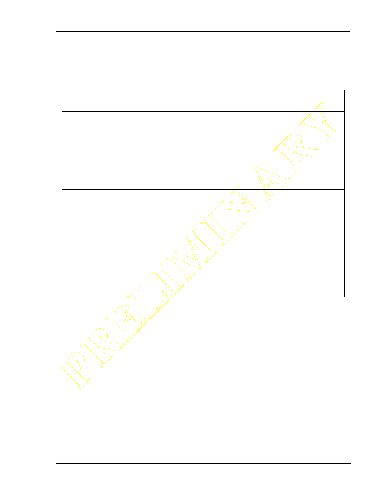
Table 1-4 Phase Lock Loop Signals
PRELIMINARY SignalName Type
PLOCK
Output
State During
Reset
Indeterminate
Signal Description
Phase Locked—PLOCK is an output signal that, when
driven high, indicates that the PLL has achieved phase
lock. After Reset, PLOCK is driven low until lock is
achieved.
PCAP
Input Input
PINIT
Input Input
EXTAL
Input Input
Note:
PLOCK is a reliable indicator of the PLL lock
state only after the chip has exited the Reset
state. During hardware reset, the PLOCK state is
determined by PINIT and the current PLL lock
condition.
PLL Capacitor—PCAP is an input connecting an off-chip
capacitor to the PLL filter. Connect one capacitor
terminal to PCAP and the other terminal to VCCP.
If the PLL is not used, PCAP may be tied to VCC, GND,
or left floating.
PLL Initial—During assertion of RESET, the value of
PINIT is written into the PLL Enable (PEN) bit of the PLL
Control Register, determining whether the PLL is
enabled or disabled.
External Clock/Crystal Input—EXTAL interfaces the
internal crystal oscillator input to an external crystal or
an external clock.
Preliminary Information
MOTOROLA
DSP56011 Technical Data Sheet, Rev. 1
1-5
Share Link: 