DSP56011 View Datasheet(PDF) - Motorola => Freescale
Part Name
Description
Manufacturer
DSP56011 Datasheet PDF : 82 Pages
| |||
Signal/Connection Descriptions
Serial Host Interface (SHI)
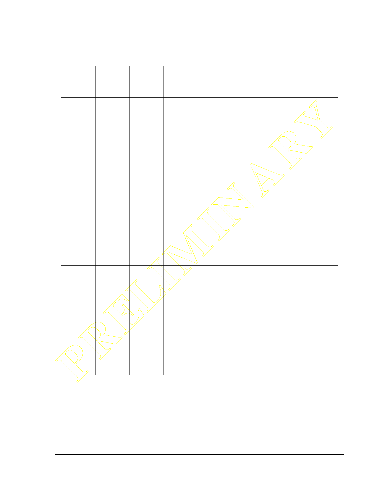
Table 1-7 Serial Host Interface (SHI) Signals (Continued)
Signal
Name
Signal
Type
State
during
Reset
Signal Description
PRELIMINARY MISO
SDA
MOSI
HA0
Input or
Output
Input or
open-
drain
Output
Input or
Output
Input
Tri-stated
SPI Master-In-Slave-Out—When the SPI is configured as a
master, MISO is the master data input line. The MISO signal
is used in conjunction with the MOSI signal for transmitting
and receiving serial data. This signal is a Schmitt-trigger
input when configured for the SPI Master mode, an output
when configured for the SPI Slave mode, and tri-stated if
configured for the SPI Slave mode when SS is deasserted. An
external pull-up resistor is not required for SPI operation.
I2C Data and Acknowledge—In I2C mode, SDA is a Schmitt-
trigger input when receiving and an open-drain output when
transmitting. SDA should be
pull-up resistor. SDA carries
tchoenndeactatefdortoI2VCCtCratnhsraocutgiohnas.
The data in SDA must be stable during the high period of
SCL. The data in SDA is only allowed to change when SCL is
low. When the bus is free, SDA is high. The SDA line is only
allowed to change during the time SCL is high in the case of
start and stop events. A high to low transition of the SDA line
while SCL is high is an unique situation, which is defined as
the start event. A low to high transition of SDA while SCL is
high is an unique situation, which is defined as the stop
event.
Tri-stated
SPI Master-Out-Slave-In—When the SPI is configured as a
master, MOSI is the master data output line. The MOSI signal
is used in conjunction with the MISO signal for transmitting
and receiving serial data. MOSI is the slave data input line
when the SPI is configured as a slave. This signal is a Schmitt-
trigger input when configured for the SPI Slave mode.
I2C Slave Address 0—This signal uses a Schmitt-trigger
input when configured for the I2C mode. When configured
for I2C Slave mode, the HA0 signal is used to form the slave
device address. HA0 is ignored when it is configured for the
I2C Master mode.
An external pull-up resistor is not required.
MOTOROLA
Preliminary Information
DSP56011 Technical Data Sheet, Rev. 1
1-13
Share Link: 