DSP56011 View Datasheet(PDF) - Motorola => Freescale
Part Name
Description
Manufacturer
DSP56011 Datasheet PDF : 82 Pages
| |||
Signal/Connection Descriptions
Interrupt and Mode Control
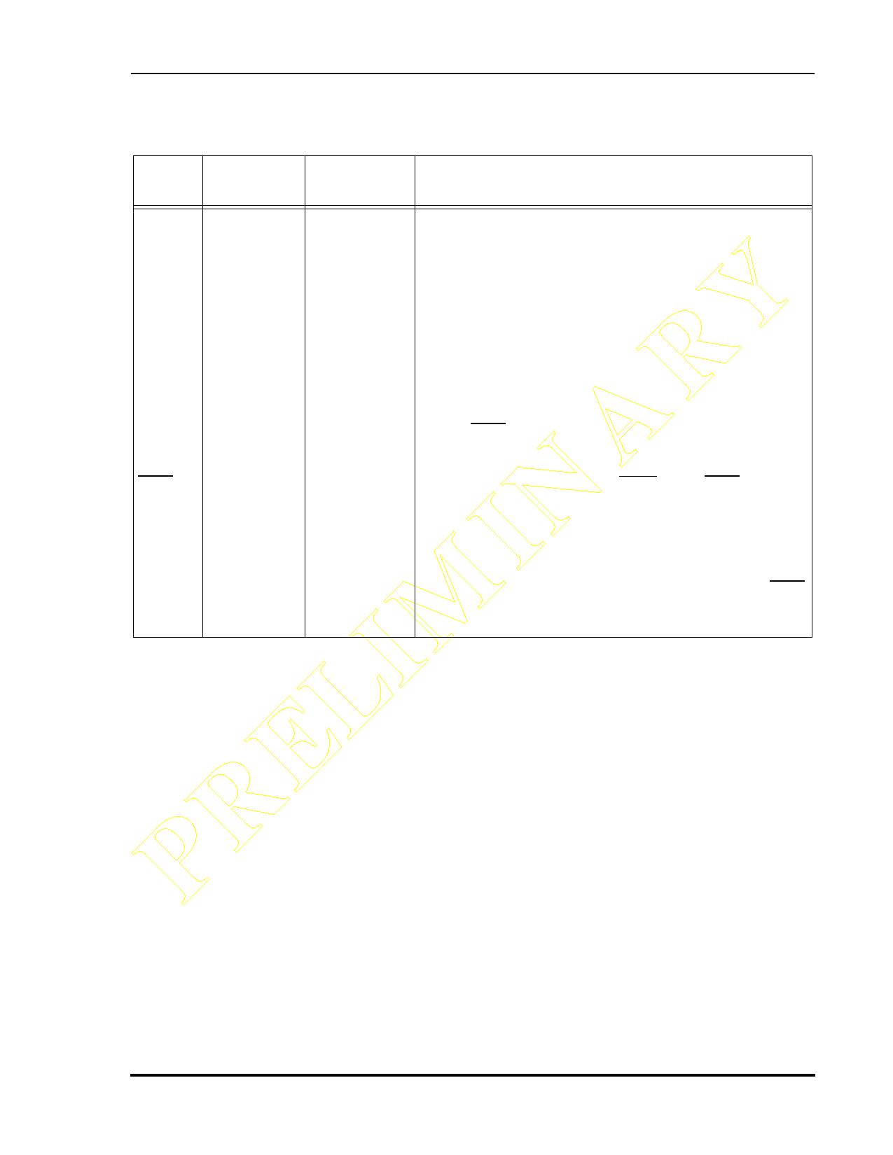
Table 1-5 Interrupt and Mode Control (Continued)
Signal
Name
Type
State During
Reset
Signal Description
PRELIMINARY MODB
IRQB
Input
Input
Input (MODB) Mode Select B—This input signal has two functions:
• to work with the MODA and MODC signals to
select the DSP’s initial operating mode, and
• to allow an external device to request a DSP
interrupt after internal synchronization.
MODB is read and internally latched in the DSP when the
processor exits the Reset state. The logic state present on the
MODA, MODB, and MODC pins selects the initial DSP
operating mode. Several clock cycles after leaving the Reset
state, the MODB signal changes to the external interrupt
request IRQB. The DSP operating mode can be changed by
software after reset.
External Interrupt Request B (IRQB)—The IRQB input is a
synchronized external interrupt request. It may be
programmed to be level-sensitive or negative-edge
triggered. When the signal is edge-triggered, triggering
occurs at a voltage level and is not directly related to the fall
time of the interrupt signal. However, as the fall time of the
interrupt signal increases, the probability that noise on IRQB
will generate multiple interrupts also increases. Hardware
reset causes this input to function as MODB.
Preliminary Information
MOTOROLA
DSP56011 Technical Data Sheet, Rev. 1
1-7
Share Link: 