DSP56011 View Datasheet(PDF) - Motorola => Freescale
Part Name
Description
Manufacturer
DSP56011 Datasheet PDF : 82 Pages
| |||
Signal/Connection Descriptions
Host Interface (HI)
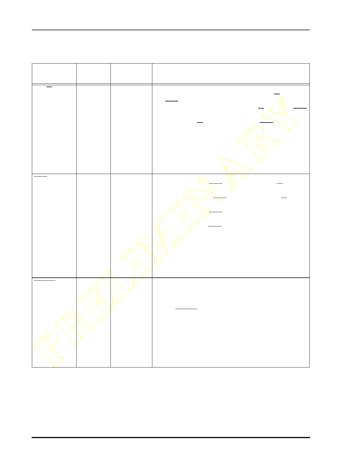
Table 1-6 Host Interface (Continued)
Signal Name
Type
State During
Reset
Signal Description
PRELIMINARY HR/W
PB11
HEN
PB12
HOREQ
PB13
Input Input
Input/
Output
Input Input
Input/
Output
Open-
drain
Output
Input
Input/
Output
Host Read/Write—This input selects the direction of data
transfer for each host processor access. If HR/W is high
and HEN is asserted, H0–H7 are outputs and DSP data is
transferred to the host processor. If HR/W is low and HEN
is asserted, H0–H7 are inputs and host data is transferred
to the DSP. HR/W must be stable when HEN is asserted.
Port B GPIO 11 (PB11)—This signal is a General Purpose
I/O signal (PB11) when the Host Interface is not being
used.
After reset, the default state for this signal is GPIO input.
Host Enable—This input enables a data transfer on the
host data bus. When HEN is asserted and HR/W is high,
H0–H7 become outputs and the host processor may read
DSP56011 data. When HEN is asserted and HR/W is low,
H0–H7 become inputs. Host data is latched inside the DSP
on the rising edge of HEN. Normally, a chip select signal
derived from host address decoding and an enable strobe
are used to generate HEN.
Port B GPIO 12 (PB12)—This signal is a General Purpose
I/O signal (PB12) when the Host Interface is not being
used.
After reset, the default state for this signal is GPIO input.
Host Request—This signal is used by the Host Interface to
request service from the host processor, DMA controller,
or a simple external controller.
Note: HOREQ should always be pulled high when it is
not in use.
Port B GPIO 13 (PB13)—This signal is a General Purpose
(not open-drain) I/O signal (PB13) when the Host
Interface is not selected.
After reset, the default state for this signal is GPIO input.
1-10
Preliminary Information
DSP56011 Technical Data Sheet, Rev. 1
MOTOROLA
Share Link: 