DSP56011 View Datasheet(PDF) - Motorola => Freescale
Part Name
Description
Manufacturer
DSP56011 Datasheet PDF : 82 Pages
| |||
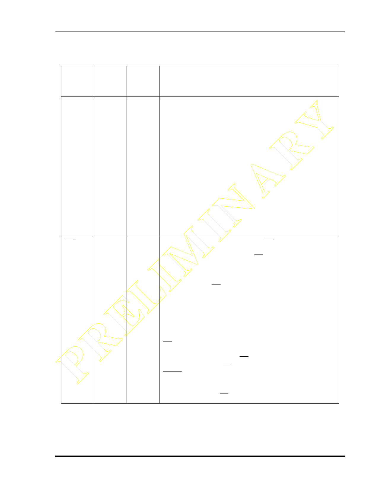
Signal/Connection Descriptions
OnCE Port
Table 1-12 On-Chip Emulation Port (OnCE) Signals (Continued)
Signal
Name
Signal
Type
State
during
Reset
Signal Description
PRELIMINARY DSO
DR
Output
Input
Pulled
high
Input
Debug Serial Output—Data contained in one of the OnCE
controller registers is provided through the DSO output signal,
as specified by the last command received from the external
command controller. Data is always shifted out the OnCE
serial port MSB first. Data is clocked out of the OnCE serial
port on the rising edge of DSCK.
The DSO signal also provides acknowledge pulses to the
external command controller. When the chip enters the Debug
mode, the DSO signal will be pulsed low to indicate
(acknowledge) that the OnCE is waiting for commands. After
the OnCE receives a read command, the DSO signal is pulsed
low to indicate that the requested data is available and the
OnCE serial port is ready to receive clocks in order to deliver
the data. After the OnCE receives a write command, the DSO
signal is pulsed low to indicate that the OnCE serial port is
ready to receive the data to be written; after the data is written,
another acknowledge pulse is provided.
Debug Request—A Debug Request (DR) input from an
external command controller allows the user to enter the
Debug mode of operation. When DR is asserted, it causes the
DSP to finish the current instruction being executed, save the
instruction pipeline information, enter the Debug mode, and
wait for commands to be entered from the DSI line. While in
Debug mode, the DR signal lets the user reset the OnCE
controller by asserting it and deasserting it after receiving an
acknowledge signal.
Note:
It may be necessary to reset the OnCE controller in cases
where synchronization between the OnCE controller and
external circuitry is lost.
DR must be deasserted after the OnCE responds with an
acknowledge on the DSO signal and before sending the first
OnCE command. Asserting DR causes the chip to exit the Stop
or Wait state. Having DR asserted during the deassertion of
RESET causes the DSP to enter Debug mode.
Note: If the OnCE interface is not in use, attach an external pull-up
resistor to the DR input.
MOTOROLA
Preliminary Information
DSP56011 Technical Data Sheet, Rev. 1
1-19
Share Link: 