CDP1805AC View Datasheet(PDF) - Intersil
Part Name
Description
Manufacturer
CDP1805AC Datasheet PDF : 30 Pages
| |||
CDP1805AC, CDP1806AC
The X designator selects one of the 16 registers R(X) to
“point” to the memory for an operand (or data) in certain ALU
or I/O operations.
The N designator can perform the following five functions
depending on the type of instruction fetched:
1. Designate one of the 16 registers in R to be acted upon
during register operations.
2. Indicate to the I/O devices a command code or device-
selection code for peripherals.
3. Indicate the specific operation to be executed during the
ALU instructions, types of tests to be performed during
the Branch instructions, or the specific operation required
in a class of miscellaneous instructions.
4. Indicate the value to be loaded into P to designate a new
register to be used as the program counter R(P).
5. Indicate the value to be loaded into X to designate a new
register to be used as data pointer R(X).
The registers in R can be assigned by a programmer in three
different ways as program counters, as data pointers, or as
scratchpad locations (data registers) to hold two bytes of
data.
Program Counters
Any register can be the main program counter; the address
of the selected register is held in the P designator. Other reg-
isters in R can be used as subroutine program counters. By
a single instruction the contents of the P register can be
changed to effect a “call” to subroutine. When interrupts are
being serviced, register R(1) is used as the program counter
for the user's interrupt servicing routine. After reset, and dur-
ing a DMA operation, R(0) is used as the program counter.
At all other times the register designated as program counter
is at the discretion of the user.
Data Pointers
The registers in R may be used as data pointers to indicate a
location in memory. The register designated by X (i.e., R(X))
points to memory for the following instructions (see Table 1):
1. ALU operations.
2. Output instructions.
3. Input instructions.
4. Register to memory transfer.
5. Memory to register transfer.
6. Interrupt and subroutine handling.
The register designated by N (i.e., R(N)) points to memory
for the “load D from memory” instructions ON and 4N and
the “Store D” instruction 5N. The register designated by P
(i.e., the program counter) is used as the data pointer for
ALU instructions F8-FD, FF, 7C, 7D, 7F, and the RLDl
instruction 68CN. During these instruction executions, the
operation is referred to as “data immediate”.
Another important use of R as a data pointer supports the
built-in Direct-Memory-Access (DMA) function. When a
DMA-ln or DMA-Out request is received, one machine cycle
is “stolen”. This operation occurs at the end of the execute
machine cycle in the current instruction. Register R(0) is
always used as the data pointer during the DMA operation.
The data is read from (DMA-Out) or written into (DMA-ln) the
memory location pointed to by the R(0) register. At the end
of the transfer, R(0) is incremented by one so that the pro-
cessor is ready to act upon the next DMA byte transfer
request. This feature in the CDP1805AC and CDP1806AC
architecture saves a substantial amount of logic when fast
exchanges of blocks of data are required, such as with mag-
netic discs or during CRT-display-refresh cycles.
Data Registers
When registers in R are used to store bytes of data, instruc-
tions are provided which allow D to receive from or write into
either the higher-order- or lower-order-byte portions of the
register designated by N. By this mechanism (together with
loading by data immediate) program pointer and data pointer
designations are initialized. Also, this technique allows
scratchpad registers in R to be used to hold general data. By
employing increment or decrement instructions, such regis-
ters may be used as loop counters. The new RLDl, RLXA,
RSXD, and RNX instructions also allow loading, storing, and
exchanging the full 16-Bit contents of the R registers without
affecting the D register. The new DBNZ instruction allows
decrementing and branching-on-not-zero of any 16-Bit R
register also without affecting the D register.
The Q Flip-Flop
An internal flip-flop, Q, can be set or reset by instruction and
can be sensed by conditional branch instructions. It can also
be driven by the underflow output of the counter/timer The
output of Q is also available as a microprocessor output.
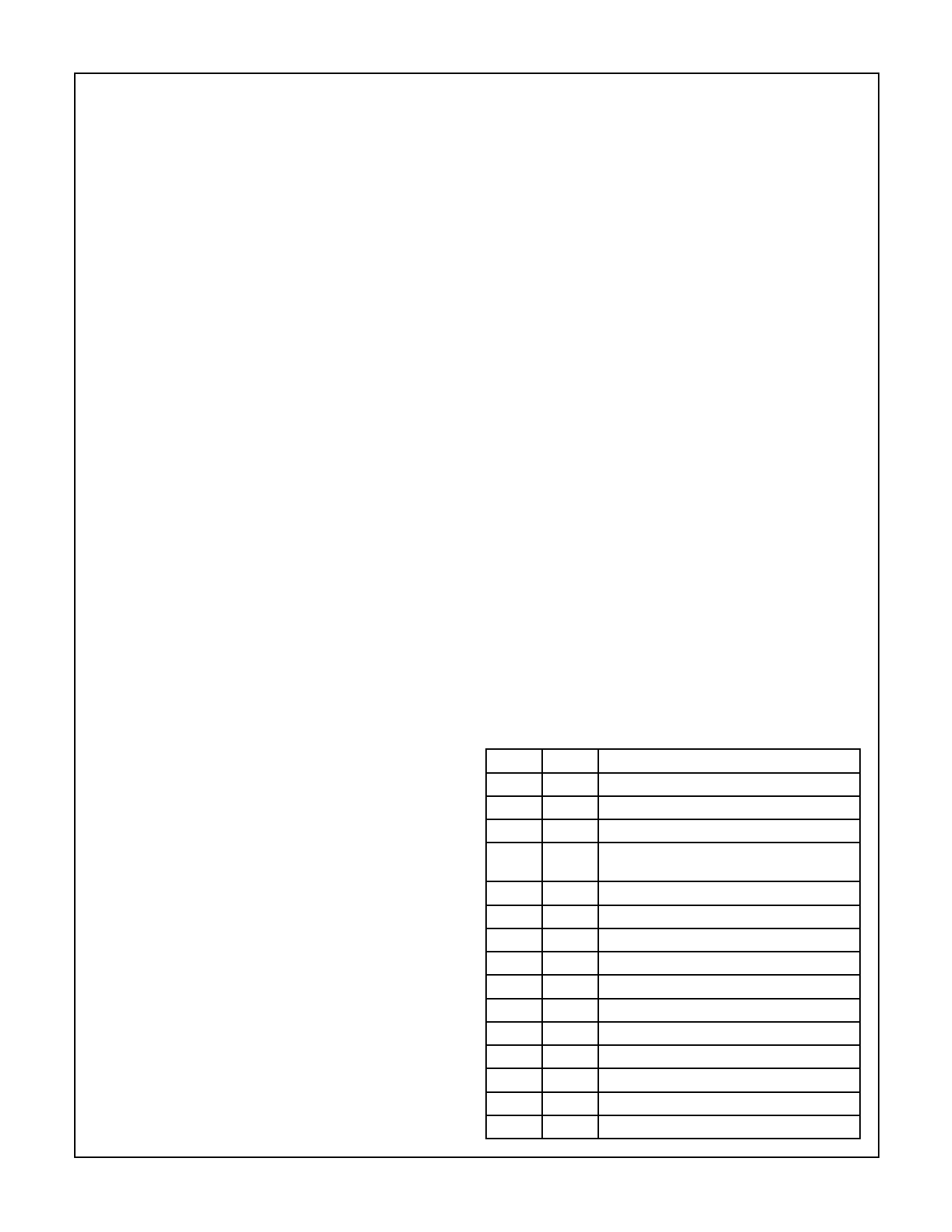
REGISTER SUMMARY
D
DF
B
R
P
X
N
I
T
Q
CNTR
CH
MIE
ClE
XlE
ClL
8 Bits Data Register (Accumulator)
1-Bit Data Flag (ALU Carry)
8 Bits Auxiliary Holding Register
16 Bits 1 of 16 Scratch and Registers
4 Bits Designates which Register is Program
Counter
4 Bits Designates which Register is Data Pointer
4 Bits Holds Low-Order Instr. Digit
4 Bits Holds High-Order Instr. Digit
8 Bits Holds old X, P after Interrupt (X is high nibble)
1-Bit Output Flip-Flop
8-Bits Counter/Timer
8 Bits Holds Counter Jam Value
1-Bit Master Interrupt Enable
1-Bit Counter Interrupt Enable
1-Bit External Interrupt Enable
1-Bit Counter Interrupt Latch
11
Share Link: 