MSC8122 View Datasheet(PDF) - Freescale Semiconductor
Part Name
Description
Manufacturer
MSC8122 Datasheet PDF : 48 Pages
| |||
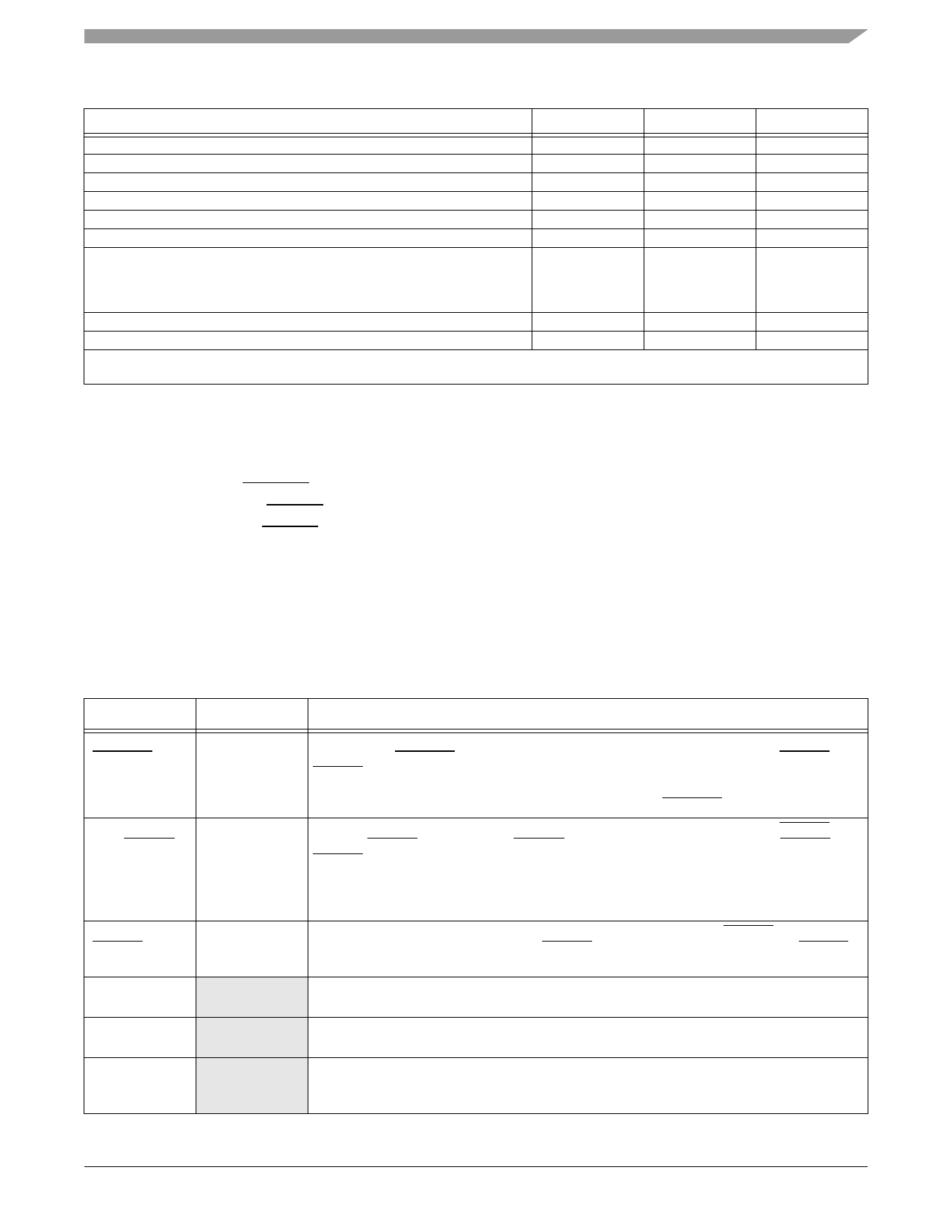
Table 9. System Clock Parameters
Characteristic
Min
Phase jitter between BCLK and CLKIN
—
CLKIN frequency
20
CLKIN slope
—
CLKIN period jitter1
—
CLKIN jitter spectrum
150
PLL input clock (after predivider)
20
PLL output frequency (VCO output)
800
• 300 MHz core
• 400 MHz core
• 500 MHz core
CLKOUT frequency jitter1
—
CLKOUT phase jitter1 with CLKIN phase jitter of ±100 ps.
—
Notes: 1. Peak-to-peak.
2. Not tested. Guaranteed by design.
Electrical Characteristics
Max
0.3
see Table 8
3
150
—
100
1200
1600
2000
200
500
Unit
ns
MHz
ns
ps
KHz
MHz
MHz
MHz
MHz
MHz
ps
ps
2.5.4 Reset Timing
The MSC8122 has several inputs to the reset logic:
• Power-on reset (PORESET)
• External hard reset (HRESET)
• External soft reset (SRESET)
• Software watchdog reset
• Bus monitor reset
• Host reset command through JTAG
All MSC8122 reset sources are fed into the reset controller, which takes different actions depending on the source of the reset.
The reset status register indicates the most recent sources to cause a reset. Table 10 describes the reset sources.
Name
Power-on reset
(PORESET)
External hard
reset (HRESET)
External soft reset
(SRESET)
Software
watchdog reset
Bus monitor reset
Host reset
command through
the TAP
Direction
Input
Input/ Output
Input/ Output
Internal
Internal
Internal
Table 10. Reset Sources
Description
Initiates the power-on reset flow that resets the MSC8122 and configures various attributes of the
MSC8122. On PORESET, the entire MSC8122 device is reset. SPLL states is reset, HRESET and
SRESET are driven, the SC140 extended cores are reset, and system configuration is sampled. The
clock mode (MODCK bits), reset configuration mode, boot mode, Chip ID, and use of either a DSI 64
bits port or a System Bus 64 bits port are configured only when PORESET is asserted.
Initiates the hard reset flow that configures various attributes of the MSC8122. While HRESET is
asserted, SRESET is also asserted. HRESET is an open-drain pin. Upon hard reset, HRESET and
SRESET are driven, the SC140 extended cores are reset, and system configuration is sampled. The
most configurable features are reconfigured. These features are defined in the 32-bit hard reset
configuration word described in Hard Reset Configuration Word section of the Reset chapter in the
MSC8122 Reference Manual.
Initiates the soft reset flow. The MSC8122 detects an external assertion of SRESET only if it occurs
while the MSC8122 is not asserting reset. SRESET is an open-drain pin. Upon soft reset, SRESET is
driven, the SC140 extended cores are reset, and system configuration is maintained.
When the MSC8122 watchdog count reaches zero, a software watchdog reset is signalled. The
enabled software watchdog event then generates an internal hard reset sequence.
When the MSC8122 bus monitor count reaches zero, a bus monitor hard reset is asserted. The
enabled bus monitor event then generates an internal hard reset sequence.
When a host reset command is written through the Test Access Port (TAP), the TAP logic asserts the
soft reset signal and an internal soft reset sequence is generated.
MSC8122 Quad Digital Signal Processor Data Sheet, Rev. 15
Freescale Semiconductor
19
Share Link: 