DSP16410C View Datasheet(PDF) - Agere -> LSI Corporation
Part Name
Description
Manufacturer
DSP16410C Datasheet PDF : 373 Pages
| |||
Data Addendum
May 2001
DSP16410C Digital Signal Processor
7 Electrical Characteristics and Requirements (continued)
7.3 Power Dissipation
The total device power dissipation is comprised of two components:
s The contribution from the VDD1 and VDD1A supplies, referred to as internal power dissipation.
s The contribution from the VDD2 supply, referred to as I/O power dissipation.
The next two sections specify power dissipation for each component.
7.3.1 Internal Power Dissipation
Internal power dissipation is highly dependent on operating voltage, core program activity, internal peripheral activ-
ity, and CLK frequency. Table 8 lists the DSP16410C typical internal power dissipation contribution for various
conditions. The following conditions are assumed for all cases:
s VDD1 and VDD1A are both 1.575 V.
s All memory accesses by the cores and the DMAU are to internal memory.
s SIU0 and SIU1 are operating at 30 MHz in loopback mode. An external device drives the SICK〈0—1〉 and
SOCK〈0—1〉 input pins at 30 MHz, and SIU〈0—1〉 are programmed to select passive input clocks (ICKA field
(SCON10[2]) and OCKA field (SCON10[6]) are cleared) and internal loopback (SIOLB field (SCON10[8]) is set).
s The PLL is enabled and selected as the source of the internal clock, CLK. Table 8 specifies the internal power
dissipation for the following values of CLK: 185 MHz and 200 MHz.
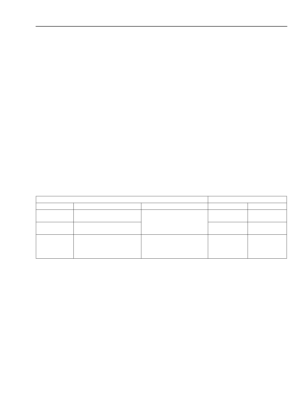
Table 8. Typical Internal Power Dissipation at 1.575 V
Type
Low-power
Standby
Typical
Worst Case‡
Condition
Core Operation
The AWAIT field (alf[15]) is set
in both cores.
Both cores repetitively exe-
cute a 20-tap FIR filter†.
Both cores execute worst-case
instructions with worst-case
data patterns.
DMAU Activity
The DMAU is operating the
MMT4 channel to continuously
transfer data.
The DMAU is operating all six
channels (SWT〈0—3〉 and
MMT〈4—5〉) to continuously
transfer data.
Internal Power Dissipation (W)
185 MHz
200 MHz
0.24
0.26
0.76
0.82
1.37
1.48
† To optimize execution speed, the cores each execute the inner loop of the filter from cache and perform a double-word data access every
cycle from separate modules of TPRAM.
‡ This is an artificial condition that is unlikely to occur for an extended period of time in an actual application because the cores are not per-
forming any I/O servicing. In an actual application, the cores perform I/O servicing that changes program flow and lowers the power dissipa-
tion.
The internal power dissipation for the low-power standby and typical operating modes described in Table 8 is repre-
sentative of actual applications. The worst-case internal power dissipation occurs under an artificial condition that
is unlikely to occur for an extended period of time in an actual application. This worst-case power should be used
for the calculation of maximum ambient operating temperature (TAMAX) defined in Section 6.3.1. This value should
also be used for worst-case system power supply design for VDD1 and VDD1A.
Agere Systems Inc.
19
Share Link: 