ADM9240 View Datasheet(PDF) - ON Semiconductor
Part Name
Description
Manufacturer
ADM9240 Datasheet PDF : 22 Pages
| |||
ADM9240
FAN INPUTS
Two inputs are provide for monitoring the condition of cooling
fans. Signal conditioning in the ADM9240 accommodates the
slow rise and fall times typical of fan tachometer outputs. The
imenitpahxueitrmsruaermseisstinuivppeupatlitesteidgnnfuraoaltmrioannfagnoefoitsuh0teptfuoatnsVtsChiCgan.taIenlxoctrheeeddieov0deetnotclVtahCmaCtp,tihnegse
must be included to keep inputs within an acceptable range.
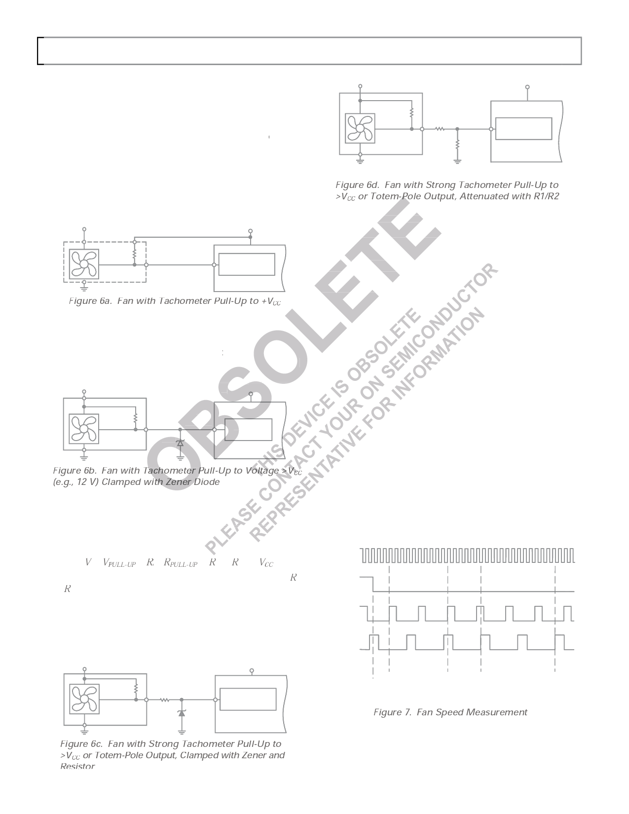
Figures 6a to 6c show circuits for most common fan tacho
outputs.
If the fan tacho output has a
connected directly to the fan
resistive pull-up
input, as shown
to
in
VFCigCuirtec6aan.
be
+12V
VCC
PULL-UP
4.7k⍀
TYP.
PULL-U
FAN1
OR FAN2
TACHO
OUTPUT
FAN SPEED
COUNTER
Figure 6a. Fan with Tachometer Pull-Up to +VCC
If the fan output has a resistive pull-up to +12 V (or other
voltage greater
a Zener diode,
athsasnhoVwCnC)i,nthFeigfuarne
output can be clamped
6b. The Zener voltage
with
should be chosen so that it is
aVbCoCu, ta0ll.o8w×inVgCfCoristhseuivtaobltlaeg. e
tgorleeartaenrctehoanf tVhIeHZbeuntelre.sAs
than
value
of
+12V *CHOOSE ZD1 VOLTAGE APPROX. 0.8 ؋ VCC VCC
PULL-UP
4.7k⍀
TYP.
TACHO
FAN1
OUTPUT OR FAN2
ZD1*
ZENER
should be chosen so that it is greater than
FAN SPEED
COUNTER
Figure 6b.
(e.g., 12 V)
Fan with
Clamped
Tachometer Pull-Up
with Zener Diode
to
Voltage
>VCC
If the fan has a strong pull-up (less than 1 kΩ) to +12 V, or a
totem-pole output, a series resistor can be added to limit the
zener current, as shown in Figure 6c. Alternatively, a resistive
attenuator may be used, as shown in Figure 6d.
R1 and R2 should be chosen such that:
2 < 2/( + 1 + 2) < V
× VPULL-UP
R
RPULL-UP
R
R
VCC
If the value of the pull-up resistor is not known, the value of R1
and R2 should be made fairly large, but not so large that the
input leakage current will cause a large voltage drop across
them.
With a pull-up voltage of 12 V and pull-up resistor less than
1 kΩ, suitable values for R1 and R2 would be 100 kΩ and
47 kΩ. This will give a high input voltage of 3.83 V.
inputs are+1s2uVpp*lCieHdOOfrSoEmZD1faVnOLoTuAGtpEuAtPsPtRhOaXt. 0e.8x؋ceVeCdC 0 toVCC
TACHO
OUTPUT
PULL-UP
TYP. < 1k⍀
OR TOTEM-POLE
R1
10k⍀
FAN1
OR FAN2
ZD1*
ZENER
FAN SPEED
COUNTER
+12V
VCC
< 1k⍀
R1*
TACHO
OUTPUT
FAN1
OR FAN2
R2*
FAN SPEED
COUNTER
*SEE TEXT
Figure 6d. Fan with Strong Tachometer Pull-Up to
>VCC or Totem-Pole Output, Attenuated with R1/R2
INPUT CURRENT LIMITING
If the fans are powered while the ADM9240 is unpowered, the
inputs of the ADM9240 will try to clamp the fan output volt-
age. In this case the input current must be limited to less than
the maximum value in the Absolute Maximum Ratings table.
The pull-up resistor of the fan tacho output may provide this
current limiting but, if its value is too low, it may be necessary
to add additional resistance in series with the fan input pins.
FAN SPEED MEASUREMENT
The fan counter does not count the fan tacho output pulses
directly, because the fan speed may be less than 1000 rpm and
it would take several seconds to accumulate a reasonably large
and accurate count. Instead, the period of the fan revolution is
measured by gating an on-chip 22.5 kHz oscillator into the
input of an 8-bit counter for two periods of the fan tacho out-
put, as shown in Figure 7, so the accumulated count is actually
proportional to the fan tacho period and inversely proportional
to the fan speed.
The monitoring cycle begins when a one is written to the start
bit (Bit 0), and a zero to the INT_Clear bit (Bit 3) of the Con-
figuration Register INT_Enable (Bit 1) should be set to one to
enable the INT output. The measurement begins on the rising
edge of a fan tacho pulse, and ends on the next-but-one rising
edge. Once the fan speeds have been measured, they will be
stored in the Fan Speed Value Registers and can be read at any
time. The measurements will be updated as long as the moni-
toring cycle continues.
22.5kHz
CLOCK
CONFIG
REG. BIT 0
FAN1
INPUT
FAN2
INPUT
FAN1
MEASUREMENT
PERIOD
FAN2
MEASUREMENT
PERIOD
START OF
MONITORING
CYCLE
Figure 7. Fan Speed Measurement
Figure 6c. Fan with Strong Tachometer Pull-Up to
R>VesCiCstoorrTotem-Pole Output, Clamped with Zener and
Rev. 2 | Page 12 of 22 | www.onsemi.com
–12–
REV. 0
Share Link: 