ADM9240 View Datasheet(PDF) - ON Semiconductor
Part Name
Description
Manufacturer
ADM9240 Datasheet PDF : 22 Pages
| |||
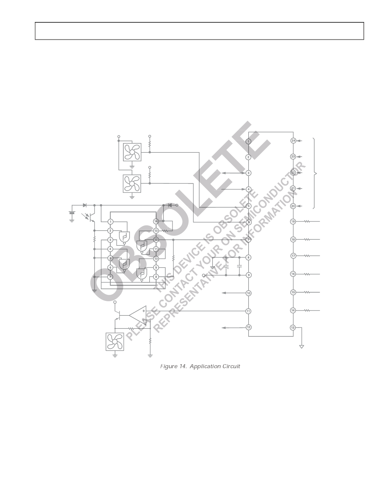
APPLICATION CIRCUIT
Figure 14 shows a generic application circuit using the
AD9240. The analog monitoring inputs are connected to the
power supplies including two processor core voltage inputs. The
VID inputs are connected to the processor voltage ID pins.
There are two tacho inputs from fans, and the analog output is
used to control the speed of a third fan. A chassis intrusion
latch with an opto-sensor is connected to the CI input. Of
course, in an actual application, every input and output may not
be used, in which case unused analog and digital inputs should
be tied to analog or digital ground as appropriate.
+12V
+3.3V
NTEST_OUT/A0
CMOS
BACKUP
BATTERY
1N914
MRD901
470k⍀
+3.3V
74HC132
1N914
+3.3V
100k⍀
A1
SDA
SERIAL BUS
SCL
FAN1
FAN2
CI
+12V
2N2219A
OP295
82k⍀
10k⍀
10k⍀
+3.3V
GNDD
10F 0.1F
+
VCC
INT
NTEST_IN/AOUT
RESET
ADM9240
ADM9240
VID0
VID1
VID2 FROM VID PINS
OF PROCESSOR
VID3
VID4
510⍀
+VCCP1
510⍀
510⍀
+2.5VIN
+3.3VIN
510⍀
+5VIN
510⍀
+12VIN
510⍀
GNDA
+VCCP2
Figure 14. Application Circuit
REV. 0
Rev. 2 | Page 17 of 22 | www.onsemi.com
–17–
Share Link: 